TM
Model 3700
M0275-01
Rev. 10/18
5-45
Lubrication and Maintenance
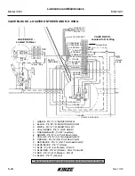
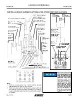
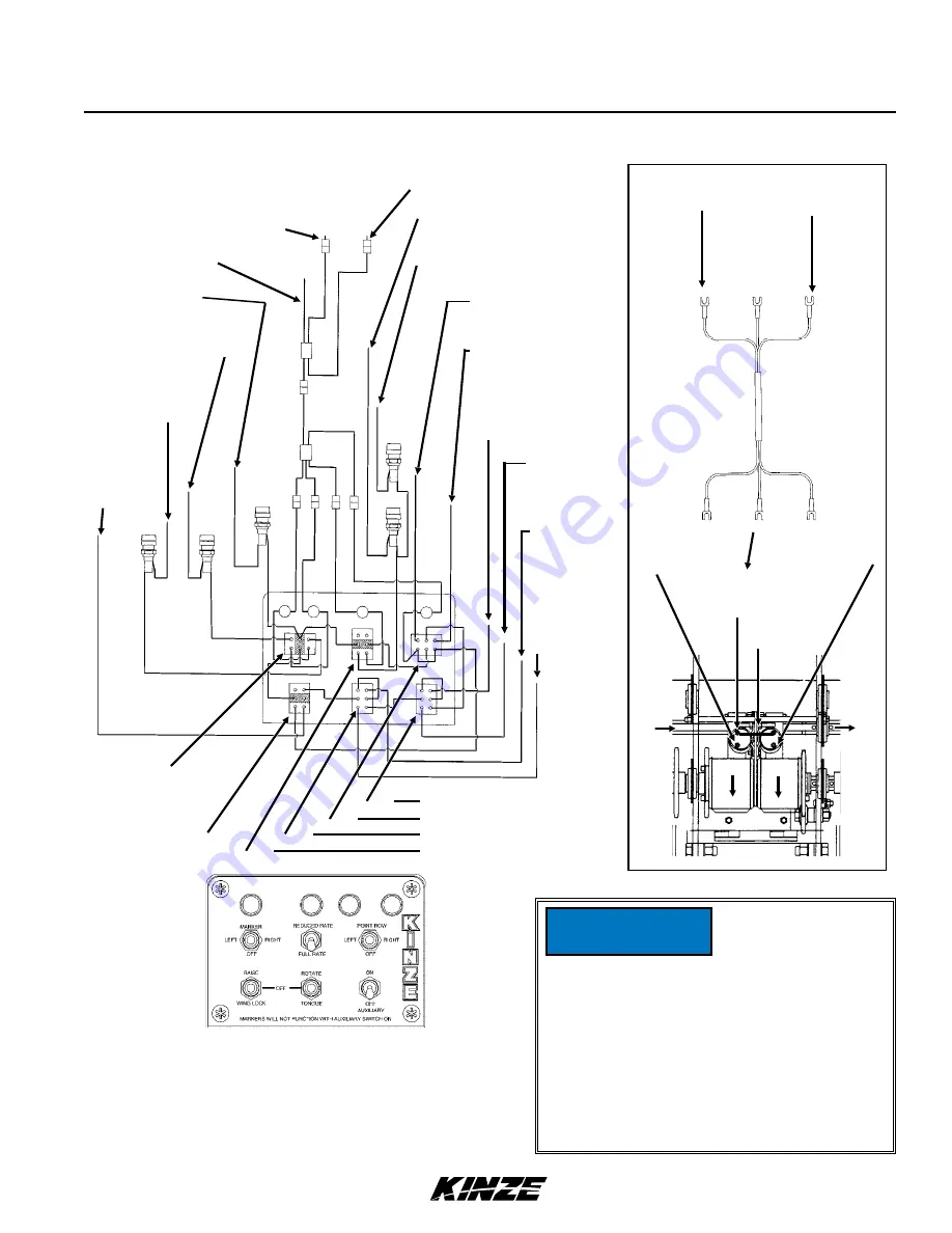
NOTE:
1. Point row and reduced rate clutch switches operate
independently from rest of control console.
2. Power to marker switch is fed through auxiliary switch and
two transport function switches. Operating any switch in
lower row disables marker function and turns off panel light
for markers.
BLUE -
L.H. To Yellow
R.H. To Red/Black
NOTE: STYLE A
With Fork
Terminals And
Contact Connectors
Shown - STYLE B
Will Have Fork
Terminals Only
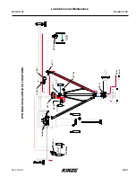
CONTROL CONSOLE SCHEMATIC (OPTIONAL TWO-SPEED POINT ROW CLUTCHES)
Pin “T” BLACK (Ground)
Pin “S” YELLOW
(L.H. Two-Speed Clutch)
Pin “U” RED/BLACK
(R.H. Two-Speed Clutch)
Pin “H” BLUE
(L.H. Marker)
Pin “O” RED
(R.H. Marker)
Pin “F”
YELLOW/RED
(NOT USED)
Pin “V”
BLUE/BLACK
(Raise)
Pin “A”
ORANGE/
RED
(Tongue)
Pin “B”
BLUE/RED
(Rotate)
Pin “C” BLACK/RED (Ground)
B L A C K ( - 1 2
VDC)
RED (+ 12 VDC)
Pin “R” BROWN
(L.H. Point Row Clutch)
Pin “G” ORANGE
(R.H. Point
Row Clutch)
Pin “W”
ORANGE/
BLACK
(Auxiliary)
Point Row
Clutch Switch
Auxiliary Switch
Raise/Wing Lock Switch
Marker Switch
Rotate/Tongue Switch
Reduced Rate Clutch Switch
Input
BLACK Ground Wire
Connects To One
Terminal
Output
RED - Point Row
Clutch Solenoid
RED -
L.H. To Brown
R.H. To Orange
BLUE -
Reduced
Rate Clutch
Solenoid
BLACK -
To Ground
Clamp
Jumper Wire
Disconnect control console
from tractor battery before
doing any electrical work
or shorting will damage
equipment. Keep wiring
harnesses away from
high temperature areas or
sharp edges. DO NOT route
wiring harnesses along
battery cables. Use cable
ties to keep wire harness
away from moving parts
on tractor and planter.
Ground connections to
tractor frame must be clean
to provide good electrical
contact.
NOTICE
Summary of Contents for 3700
Page 2: ......
Page 3: ......
Page 4: ......
Page 18: ...This page intentionally left blank ...
Page 54: ...This page intentionally left blank ...
Page 102: ...This page intentionally left blank ...
Page 119: ...This page intentionally left blank ...


