6
-
3-poInt hItch ImpLement And LoAdeR opeRAtIon
6
-
ds4110(hs) / ds4510(hs)
6
6
-
3-poInt hItch ImpLement And LoAdeR opeRAtIon
6
-
ds4110(hs) / ds4510(hs)
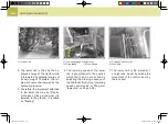
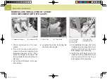
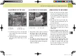
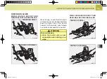
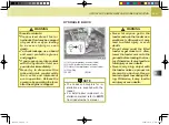
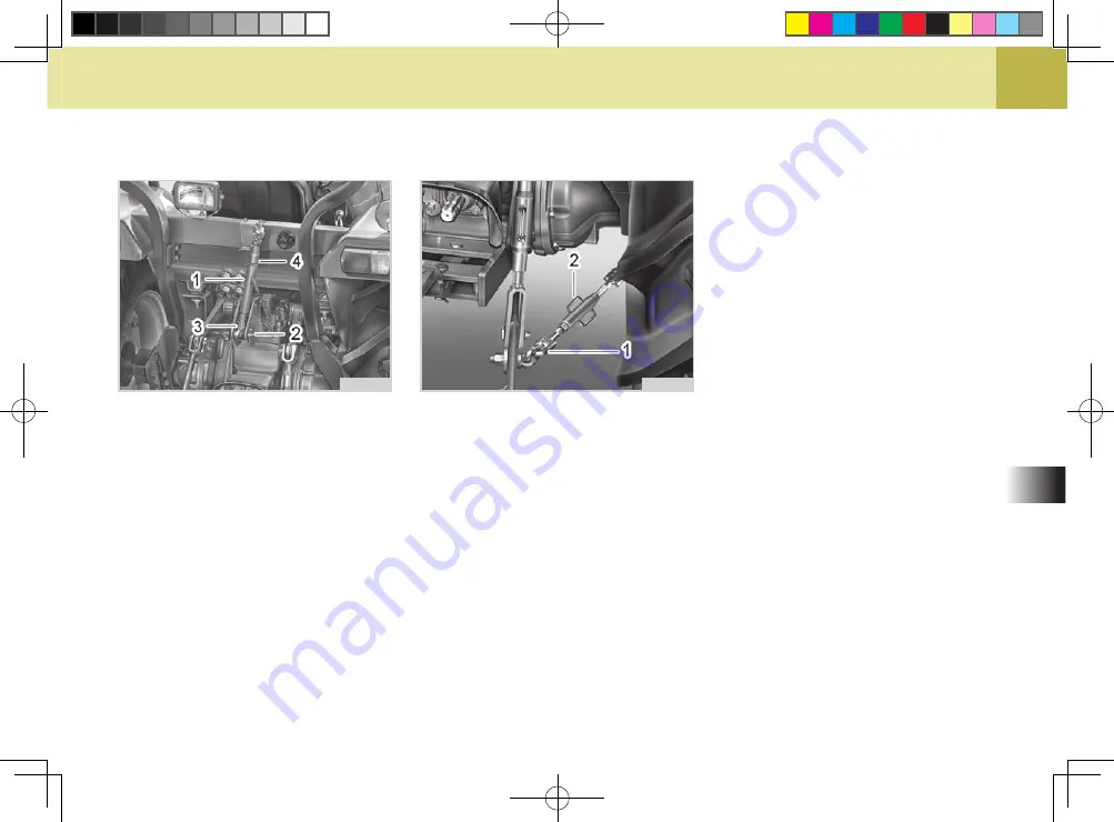
(1) top Link (2) set pin
(3) Lynch pin (4) top Link hook
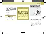
1. Install the top link to the desired
hole, install the set pin and lynch
pin securely.
2. tighten the lock nut on the top link
securely after adjusting top link
length.
H61O607A
adjustment of top link
H61O601A
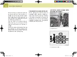
adjustment of stabilizeR
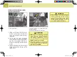
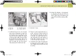
(1) check chain
(2) turn buckle
1. Adjust the check chain to control
horizontal sway of the implement.
It is also used to set the imple-
ment on the back of the tractor in
center.
2. to adjust the check chain, pull out
the turn buckle and adjust it until
the desired transverse moving dis-
tance is obtained.
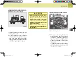
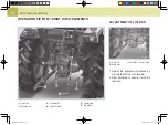
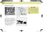
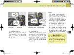
dismounting the implement
1. park the tractor with the imple-
ment on the level ground and low-
er the implement all the way down.
Install the implement support as
needed.
2. disconnect the top link and low-
er links from the implement by re-
moving the pins.
3. be sure to insert the set pins,
lynch pins and snap pins back to
the implement securely to keep
those safe.
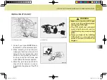
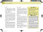
4. stop the engine and move the re-
mote hydraulic control lever back
and forth to relief the hydraulic
pressure in the system before dis-
connecting hydraulic couplers.
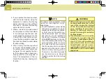
5. put the top link back to its hook.
hold both lower links together with
a rubber band. otherwise, the low-
er links can contact with rear tires
and cause damage to the lower
links and tires while driving.
M50-EU-06.indd 5
2009-09-15 오전 9:51:07
Summary of Contents for DS4110
Page 2: ...M50 EU 00 indd 2 2009 09 14 2 22 41...
Page 30: ...MEMO MEMO M50 EU 01 indd 20 2009 09 17 1 16 46...
Page 36: ...MEMO MEMO M50 EU 02 indd 6 2009 09 28 6 14 23...
Page 44: ...MEMO MEMO M50 EU 03 indd 8 2009 10 08 8 29 38...
Page 105: ...MEMO MEMO M50 EU 05 indd 26 2009 09 28 6 13 27...
Page 159: ...MEMO MEMO M50 EU 07 indd 40 2009 09 28 6 11 58...
Page 170: ...10 INDEX INDEX 10 2 10 M50 EU 10 indd 1 2009 09 15 10 31 57...

