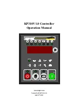
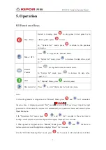
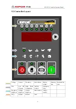
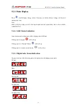
background image


KP310V1.0 Controller 

Operation Manual 


V

A

R


Model  KP310V1.0

V

O

RUN

V

A

R


Model  KP310V1.0

V

O

RUN


www.kipor.com


Version No.

KP310.1.1.0 

July 20

th

, 2011   


Summary of Contents for KP310V1.0

Page 1: ...KP310V1 0 Controller Operation Manual V A R Model KP310V1 0 V O RUN V A R Model KP310V1 0 V O RUN www kipor com Version No KP310 1 1 0 July 20th 2011 ...

Page 2: ... Parameter Set 15 8 1 Parameters Set list 16 8 2 Programmable output list 21 8 2 1 Remote set 21 8 2 2 Set Input 22 8 3 Programmable output list 23 9 Commission 24 10 Applications 24 11 Installations 25 12 Trouble shooting 26 13 Serial Communication 26 13 1 Physical Layer of Communication Protocol 27 13 2 Enquiry Response Period 27 13 3 Comm RTU 28 13 3 1 Address field 28 13 3 2 Function field 28 ...

Page 3: ...ital numbers convenient to test genset by touch buttons Manual remote start and stop genset RS232 interface with PC to run and monitor genset RS485 interface to remote monitor genset Applied to 3 phase 4 line 3 phase 3 line 1 phase 2 line double voltage power sources Monitor and display three phase voltage three phase current frequency revolutions and battery voltage Fault alarms including over vo...

Page 4: ...le phase two line Double voltage output simultaneously Double voltage output alternative Primary current 1A 900A Parameters Set Secondary current 5mA Current measurement Precision level 2 0 Frequency range 20 70HZ voltage 15V Frequency measurement Precision level 0 5 Voltage range 5 50V Max frequency 10000Hz Revolution measurement Flywheel tooth 1 500 Fuel output relay 15A 12VDC Start output relay...

Page 5: ...t Parameters Set Press to enter Parameters Set selection menu Note 1 when the generator is stopped and in Manual Mode press and for 5 seconds at the same time it displays password Test mode If user doesn t input the right password in 60 seconds the system will automatically exit password menu and enters System Operation menu 2 In Parameters Set menu press and for 5 seconds in the same time to back...

Page 6: ...ear alarm of air filter maintenance and reset it 7 In the Running Time mode press for 5 seconds it will clear running time and reset it 8 Press and for 5 seconds until the signal twinkles which shows that system has blocked some protection functions over under frequency over under voltage then press and for 5 seconds until the signal stop flickering which shows that system has restored the protect...

Page 7: ...V A R Model KP310V1 0 V O RUN Voltage Current Frequency Revolutions Battery voltage Running time Maintenance time Run Low Oil Pressure High Water Temperature Starting Failure Emergency Stop Frequency High Low Voltage High Low Current High Low Maintenance Charge Failure Stop Manual Remote Start ...

Page 8: ...te is also available with RS232 Port 5 2 1 1 LED Status Indication Genset status and working mode will be displayed in LED Panel When genset is stopped will be lit up When genset is in Manual Mode will be lit up When genset is in remote control mode will be lit up 5 2 1 2 Digital tube Status Indication If genset switches to the following status the digital tube will display genset status Preheat S...

Page 9: ...er which shows as following Voltage Three phase four line Three phase three line Single phase two line Two phase three line Double voltage output alternative 120V output equals to single phase two line 240V output equals to two phase three line Current Three phase four line ...

Page 10: ...three line Double voltage output alternative 120V output equals to single phase two line 240V output equals to two phase three line Frequency Revolution Note If the Revolution low is set as zero then the speed won t be displayed Battery voltage Running time Maintenance Time Oil filter Fuel filter ...

Page 11: ...OP TO STANDBY PREHEAT TIME SECURITY DELAY AC SYSTEM CURRENT RATIO LOW FREQUENCY HIGH FREQUENCY UNDER VOLTAGE OVER VOLTAGE OVER CURRENT 1 OVER CURRENT 2 FAULT DELAY OF UNDER FREQUENCY FAULT DELAY OF OVER FREQUENCY FAULT DELAY OF UNDER VOLTAGE FAULT DELAY OF OVER VOLTAGE FAULT DELAY OF OVER CURRENT 1 FAULT DELAY OF OVER CURRENT 2 FAULT DELAY OF OVER CURRENT 3 FAULT DELAY OF OVER CURRENT 4 UNDER VOLT...

Page 12: ...e is 100 While the value twinkles press or to increase or decrease the value After inputting the value press to confirm and save the value Press to get back to Parameters Set menu 5 3 Manual Operation When the KP310V1 0 controller is working it is initialized to Manual Mode with indicator lighting Press or turn the ignition lock to start genset Start steps Preheat relay output meanwhile the prehea...

Page 13: ...n If the preheating time is set as zero the relay won t output After preheating the preheating relay stop working the fuel relay and starting relay begin to output The maximum starting timer begins to count down If genset can start successfully during the countdown the starting relay stops outputting If failed the fuel relay and starting relay stop outputting After starting genset the security del...

Page 14: ... battery voltage When the battery voltage is lower than the set value battery LED twinkles 6 Charging faults When the charging voltage is lower than the set value battery LED twinkles 6 2 Time delayed stop alarms After detecting the time delayed stop alarms relevant LED twinkles and genset will be stopped after a delayed time No Type Description 1 Over Current 1 If genset current is larger than Ov...

Page 15: ...genset will be stopped instantly Customers can set values to disable the protection 5 Over Frequency If genset frequency is larger than the set value over frequency LED twinkles genset will be stopped instantly 6 Under Frequency If genset frequency is lower than the set value under frequency LED twinkles genset will be stopped instantly 7 Low Oil Pressure If oil pressure is lower than the set valu...

Page 16: ...tput 1 0mm2 Rated current 15A provide B by port 3 5 Start relay output 1 0mm2 Rated current 15A provide B by port 3 6 Dual voltage selection input 1 0mm2 Active if lower voltage circuit is closed 7 Ignition lock start input 1 0mm2 Connect to the ignition lock start terminal 8 Remote control input 1 0mm2 Remote input terminal low voltage active 9 Revolution sensor input 1 0mm2 10 Revolution sensor ...

Page 17: ...e detecting input 1 0mm2 Connect with CT secondary wiring Rated current 5mA 27 Current transformer common terminal 1 0mm2 Refer to the description on the back of controller 28 Generator N phase voltage input 1 0mm2 Connect with N wire 29 Generator C phase voltage input 1 0mm2 Connect with the C wire 4A fuse 30 Generator B phase voltage input 1 0mm2 Connect with the B wire 4A fuse 31 Generator A ph...

Page 18: ... Genset Frequency when starter is tripping 4 Tripping charging voltage 0 400 0 1V 50 Charging alternator voltage when starter is tripping 5 Starting timer 1 100 0 1s 5 Genset start timer 6 Tripping oil pressure delay 1 100 0 1s 5 Oil pressure when starter is tripper 7 Maximum starting time 1 100 0 1s 30 Average starter working Time 8 Under RPM 0 6000 1rpm 0 Engine under speed 9 Over RPM 0 6000 1rp...

Page 19: ...5 0 1A 450 Generator pre overload 22 Over Current 2 0 65535 0 1A 500 Generator overload 23 Under Frequency Fault Delay 0 65535 0 1S 20 Generator output under frequency Stop Delay 24 Over Frequency Fault Delay 0 65535 0 1S 5 Generator output over frequency Stop Delay 25 Under Voltage Fault Delay 0 65535 0 1S 20 Generator output voltage low Stop Delay 26 Over Voltage Fault Delay 0 65535 0 1S 5 Gener...

Page 20: ...pen 5 Remote Start Stop Normally Closed 38 Remote start delay 0 65535 0 1s 50 In remote mode timing from give start signal to successfully start 39 Remote Stop Delay 0 65535 0 1s 50 In remote mode timing from give Stop signal to successfully stop 40 Remote start Times 1 10 1 3 In remote mode start times in the normal range 41 Input 1 Type 0 3 1 0 0 Warning Normally Open 1 Warning Normally Closed 2...

Page 21: ...Genset Running 6 Genset Electric Parameters Normal 7 System Warning Alarm 8 System Delay Stop Alarm 9 System Stop Alarm 10 System Alarm 11 Manual Mode 12 Remote Mode 13 Oil Filter Overtime 14 Fuel Filter Overtime 15 Air Filter Overtime 16 Start Failure Idle 47 Start idle Time 0 65535 0 1s 0 Timing from start idle running to rated RPM 48 Stop idle Time 0 65535 0 1s 0 Timing from stop idle running t...

Page 22: ...rent Gain 0 2047 1 1024 Regulate the Gain to display the same L2 phase current on the controller with the actual voltage 55 L3 Phase current Gain 0 2047 1 1024 Regulate the Gain to display the same L3 phase current on the controller with the actual voltage 56 L12 Line Voltage Gain 0 2047 1 1024 Regulate the Gain to display the same L12 Line Voltage on the controller with the actual voltage 57 L23 ...

Page 23: ...mote start normally open In the Remote mode after Terminal 8 is closed low potential genset start after Remote start delay parameters can be setup Terminal 8 open high potential genset won t stop 8 2 1 2 Remote start normally closed In the Remote mode after Terminal 8 is open high potential genset start after remote start delay parameters can be setup Terminal 8 close low potential genset won t st...

Page 24: ...o Contents Note 1 0 Warning Normally Open 2 1 Warning Normally Closed 3 2 Stop normally open 4 3 Stop normally closed Normally Open in the default state input signal open high potential input signal close low potential is valid Normally Closed in the default state input signal close low potential input signal open high potential is valid 8 2 2 1 Warning Normally Open After Terminal is closed low p...

Page 25: ...et in the norminal running state 7 6 genset electric parameters normal Output when genset voltage frequency is normal 8 7 system Warning alarm Output when system Warning alarm 9 8 system delay stop alarm Output when system delay stop alarm 10 9 system Stop alarm Output when system delay alarm 11 10 system alarm Output when system alarm 12 11 manual mode Output when system in the manual mode 13 12 ...

Page 26: ...lve connections press start button genset will start if everything is OK genset will be in the idle state for a while if idle running is available then genset will run normally In this period check if everything is OK for example voltage frequency If there are some abnormal situations stop genset check the connection refer to the Manual 7 Please contact with us if you need help 10 Applications 1 2...

Page 27: ...3 4 5 6 7 8 9 10 11 12 13 14 15 16 17 18 1 2 3 4 5 6 7 8 9 10 11 12 13 14 15 16 17 18 19 21 20 22 23 24 25 26 27 28 29 30 31 KP310V1 0 GENSET CONTROLLER A B C N Genset Voltage IA IB IC ICOM Current Rated 5mA DIR TXD RXD Comm_GND Comm_VCC B B EM Stop Fuel High Temp Oil Press Aux_In1 Aux_In2 Remote 120 240 Select Crank Start sw Bat Charge Preheat Aux_Out1 Aux_Out2 MPU ...

Page 28: ... sensor and connections Alarm Stop during running Check relevant connections Check Set Input parameters start failure Check fuel pipe and connections Check batteries Check RPM sensor and connections Refer to the Engine s Manual No start signals Check start motor and connections Check batteries RS232 failure Check the connections Check if COM port is right setup Check connections between RS232 TXD ...

Page 29: ...8 Stop bit 1 Data period 5ms Frame frame period 100ms Comm timeout 200ms Bit1 Bit2 Bit3 Bit4 Bit5 Bit6 Bit7 Bit8 Bit9 Bit10 Start D0 D1 D2 D3 D4 D5 D6 D7 Stop 13 2 Enquiry Response Period The host starts enquiring actively and the slave responds passively as following Address Function code Comm data Data adjustment Host inquiry Address Function code Comm data Data adjustment Slave response ...

Page 30: ...ication between PC and controller Low byte is before the high byte 13 3 2 Function field Function code is the Host operation code and reply code from Host 13 3 3 Data field Value is the actual bytes of data 3 2 Data type 2Byte 13 3 4 Data CRC field Data check uses CRC16 CCITT as standard to check all data in MODBUS except data in check field Low byte stands after high byte The host machine sends m...

Page 31: ... 0xddcd 0xad2a 0xbd0b 0x8d68 0x9d49 0x7e97 0x6eb6 0x5ed5 0x4ef4 0x3e13 0x2e32 0x1e51 0x0e70 0xff9f 0xefbe 0xdfdd 0xcffc 0xbf1b 0xaf3a 0x9f59 0x8f78 0x9188 0x81a9 0xb1ca 0xa1eb 0xd10c 0xc12d 0xf14e 0xe16f 0x1080 0x00a1 0x30c2 0x20e3 0x5004 0x4025 0x7046 0x6067 0x83b9 0x9398 0xa3fb 0xb3da 0xc33d 0xd31c 0xe37f 0xf35e 0x02b1 0x1290 0x22f3 0x32d2 0x4235 0x5214 0x6277 0x7256 0xb5ea 0xa5cb 0x95a8 0x8589 ...

Page 32: ...CITT code Input p mouse cursor points to first byte DataLen data length Output CRC16CCITT Unsigned int CRC16CCITT unsigned char p unsigned int DataLen Unsigned int crc16 0 Unsigned int i Unsigned char b for i 0 i DataLen i b unsigned char crc16 8 crc16 8 crc16 CRC16CCITT b p p return crc16 ...

Page 33: ... 11 12 13 14 15 16 17 18 19 21 20 22 23 24 25 26 27 28 29 30 31 KP310V1 0 GENSET CONTROLLER A B C N IA IB IC ICOM DIR TXD RXD Comm_GND Comm_VCC B B EM Stop Fuel High Temp Oil Press Aux_In1Aux_In2 Remote 120 240 Select Crank Start sw Bat Charge PreheatAux_Out1 Aux_Out2 MPU A B C N U V W N QF Generator Load ...

Page 34: ... 15 16 17 18 19 21 20 22 23 24 25 26 27 28 29 30 31 KP310V1 0 GENSET CONTROLLER A B C N IA IB IC ICOM DIR TXD RXD Comm_GND Comm_VCC A B C U V W QF B B EM Stop Fuel High Temp Oil Press Aux_In1 Aux_In2 Remote 120 240 Select Crank Start sw Bat Charge Preheat Aux_Out1 Aux_Out2 MPU Generator Load ...

Page 35: ...2 13 14 15 16 17 18 19 21 20 22 23 24 25 26 27 28 29 30 31 KP310V1 0 GENSET CONTROLLER A N IA ICOM DIR TXD RXD Comm_GND Comm_VCC A N U N QF B B EM Stop Fuel High Temp Oil Press Aux_In1 Aux_In2 Remote 120 240 Select Crank Start sw Bat Charge Preheat Aux_Out1 Aux_Out2 MPU Generator Load ...

Page 36: ... 21 20 22 23 24 25 26 27 28 29 30 31 KP310V1 0 GENSET CONTROLLER A B N IA IB ICOM DIR TXD RXD Comm_GND Comm_VCC A B N U V W QF B B EM Stop Fuel High Temp Oil Press Aux_In1 Aux_In2 Remote 120 240 Select Crank Start sw Bat Charge Preheat Aux_Out1 Aux_Out2 MPU 4 2 Phase 3 Line Generator Load ...

Reviews: