17
3.3 Electrical components
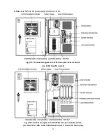
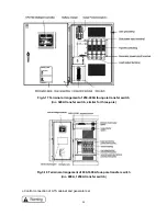
This part explains the standard and optional parts of ATS cabinet electrical controlling system (refer
to figures from 4-7 to 4-9).
Incorrect calibration or regulation may cause death, serious personal injury and/or equipment
damage. The one who calibrates or regulates must be qualified technicians.
There is electric shock hazard in the cabinet and behind the door. Opening the door may cause
serious personal injury. So special attention must be paid that body, tools, jewelries, clothes, hair
etc. should be away from the electric contactor.
Standard components:
A. KPD100 intelligent controller
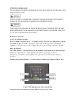
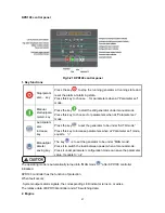
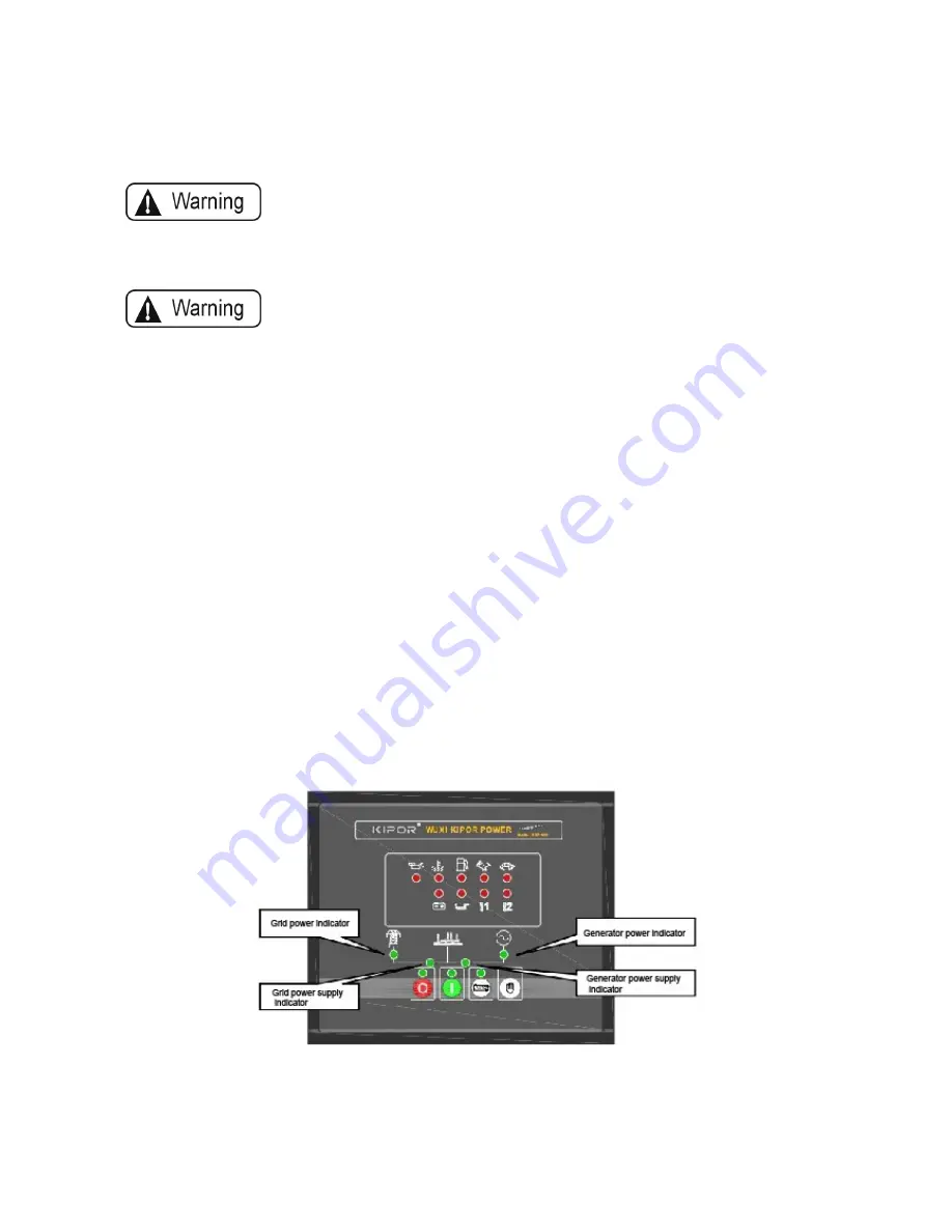
KPD100 intelligent controller (fig.3-11) is installed on the ATS cabinet. ATS switching is controlled
by KPD100 intelligent controller obtaining the built-in ATS controlling function (with default
installation on the generator set). Green light on the display panel indicates the state of transfer
switch as following:
Grid power indicator – it turns light when the grid voltage is normal and turns red when abnormal.
Grid power supply indicator – it turns light when the grid is supplying power to load.
Generator power indicator– it turns light when the generator is normal and turns red when
abnormal.
Generator power supply indicator - it turns light when the generator is supplying power to load.
Fig.3-11 ATS display panel on the cabinet door
Details about KPD100 intelligent controller please see Part 5 of this chapter.
Summary of Contents for KPEC Series
Page 1: ...1 KPEC Series User Manual of ATS Cabinet www kipor com...
Page 38: ...6 Attachment 1 Electric principle figure four figures together...
Page 39: ......
Page 40: ...2 User wiring diagram six together...
Page 41: ......
Page 42: ......
Page 43: ...3 Definition of ATS cabinet remote control aviation plug option...


