29
Take four-pole 200 ampere ATS cabinet as a sample to make a brief introduction of ATS test run
:
Ensure correct wiring, no load to ATS cabinet and generator set normal
¾
Trial run at manual mode
:
A. Turn on the power switch of KPD100 controller on generator set, it enters into "Manual mode"
automatically.
B. Press the key
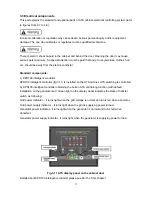
on the panel. After generator set start, "Generator set power indicator lamp"
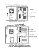
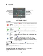
on ATS panel (Fig. 3-10
),
press the key
,
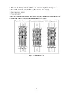
ATS will switch to generator set, then the status
window B of transfer switch will display “ON”
(
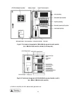
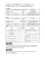
Fig. 3-13
),
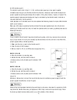
"Generator set power supply indicator
lamp " on controller panel will be light.
(
Fig3-11
)。
C. Close the grid power switch
(
User supply
),
the "Grid power indicator lamp " on controller panel
will be light
(
Fig. 3-10
),
press the key
, ATS switch to grid power, the state window A of
transfer switch will display “ON”
(
Fig. 3-12
)
, "Grid power supply indicator "on controller panel will
on
(
Fig. 3-11
)
“Generator power indicator lamp“ will go out.
D. Continuously press the key “Manual mode
”
,
ATS will repeat the action of B .C items
E
:
Press the key
, generator set stops running. Disconnect the grid power, “test run under
manual mode" has been finished
¾
Trial run at automatic mode:
A. Turn on the power switch, it enters into "Manual mode
" automatically. Press the key
. It
enter into “auto mode
”
,
the "auto indicator lamp" on control panel will be light. The controller will
realize the abnormality of grid power, then start the generator set automatically. After that,
"Generator power indicator lamp" will be light
(
Fig. 3-11
),
ATS will switch to generator set power,
the state window B of transfer switch displays “ON”
(
Fig.3-13
),
"Generator power indicator lamp"
on controller panel will be light(Fig. 3-11
)。
B. Close the switch of grid power (User supply). "Grid power indicator lamp" on controller panel will
be light
(
Fig. 3-11
),
KDP100 controller controls ATS to switch to grid power. The status window A
of transfer switch will display “ON”
(
Fig3-12
),
"Generator power supply indicator lamp" will be on
(Fig. 3-11
)
and "Generator power indicator lamp" will go out. Generator set will stop automatically
after cooling delay, and keep in standby state.
C. Open the switch of grid power (User supply), KPD100 controller will realize abnormality of grid
power, then start the generator set automatically. ATS will repeat the action above.
D. Press the key
, generator set stops running. Disconnect the grid power, "trial run under
manual mode" has been finished
Summary of Contents for KPEC Series
Page 1: ...1 KPEC Series User Manual of ATS Cabinet www kipor com...
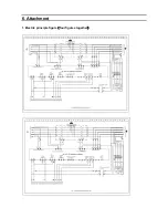
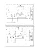
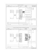
Page 38: ...6 Attachment 1 Electric principle figure four figures together...
Page 39: ......
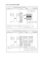
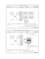
Page 40: ...2 User wiring diagram six together...
Page 41: ......
Page 42: ......
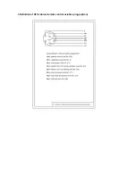
Page 43: ...3 Definition of ATS cabinet remote control aviation plug option...


