background image


5


1. ATS general introduction 


1.1 Definition and working principle 

ATS is short for automatic transfer switch. It is mostly used in emergency power supply system, 

automatically switching the load circuit from one power supply to another (standby power supply) 

and insuring the continuous and reliable running of important load. 


1.2 Applications 

(1) Switch between the grid and standby power supply (i.e. generator set) 

Applicable to the system of standby power supply (i.e. generator set) or one-way power grid. The 

transfer switch can automatically detect power fault of the grid, send start signal to standby 

generator set and switch the load. 

(2) Switch between generators 

Applicable to the system with several generator sets as the main power supply. If the main 

generator set goes wrong, the transfer switch will send start signal to the second generator set and 

switch the load.   

(3) Switch between the grids 

Applicable to the multiple power grids without a standby generator set. If one grid goes wrong, the 

transfer switch will automatically connect the load to the second one. 

(4) Triplicate power supply 

A. Applicable to the single standby power supply and dual grid system. 

The grid transfer switch controls the power supplied by dual grid according to the predetermined 

order. If power supply of both the grids goes wrong, the transfer switch will send start signal to 

standby generator set and switch the load. 

B. Applicable to the single grid and dual standby power supply system. 

If the grid goes wrong, the transfer switch will send start signal to the main standby generator set 

and switch the load. If the main standby generator set goes wrong, the transfer switch will send 

start signal to the second standby generator set and switch the load. 


1.3 ATS switching mode 

(1) Open-loop switching (in-phase switching, power-off switching) 

Off after On is the basic switching mode: Firstly switch off the first power supply, and then switch on 

the second power supply. Users can monitor both the power supplies and start switch with the 

in-phase monitor (or sync check function) in the controller, so as to avoid the problem of 

out-of-phase.  

Application: emergency power system, regulation specified power system and optional standby 

power system; resistive load; small motor load.   

Summary of Contents for KPEC Series

Page 1: ...1 KPEC Series User Manual of ATS Cabinet www kipor com...

Page 2: ...el definition for KPEC series ATS cabinet 3 Operation manual for KPEC series ATS cabinet 3 1 Introduction for KPEC series cabinet 3 2 Cabinet 3 3 Electrical component Standard component Optional compo...

Page 3: ...l can have the key High voltage in the cabinet may cause serious shock injury so all the maintenance and repair concerning the transfer switch should only be done by electrician or authorized personne...

Page 4: ...o not operate the machine with mental or physical fatigue or after drinking or taking medicine Warn that incorrect maintain or parts replacing may cause death serious personal injury or equipment dama...

Page 5: ...ally connect the load to the second one 4 Triplicate power supply A Applicable to the single standby power supply and dual grid system The grid transfer switch controls the power supplied by dual grid...

Page 6: ...ATS controller The controller is generally used for inspecting the work condition of monitored power supply double lines When the monitored power supply goes wrong e g phase failure under voltage loss...

Page 7: ...transfer switching ATS accords with this standard and has passed the certificate of KEMA testing institute 2 Integrated design 3 Dual interlock of mechanical and electrical ATS has reliable mechanica...

Page 8: ...400A 630A 800A 1000A 1250A 1600A 2000A 2500A 3000A 3200A The types of 26A 50A 75A are equipped with ABB contactor 4 Voltage code A single phase 110V 120V B single phase 220V 240V C three phase three l...

Page 9: ...DC output is the same to the option in control type with the maximum output of 6A 9 Distributed by the factory Remark KPEC series ATS cabinet can obtain the optimal power switching effect when using t...

Page 10: ...ll never power on two supply lines simultaneously The grid line works with a generator set emergency power supply as standby power and loads connect to the ATS common terminal see fig 3 2 The controll...

Page 11: ...11 Fig 3 2 Wiring diagram for 200A 4 pole transfer switch Fig 3 3 ATS power supply diagram grid power load Fig 3 4 ATS power supply diagram generator power load...

Page 12: ...Refer to fig 3 5 and fig 3 1 for dimension and outline drawing for IP32 cabinet Refer to fig 3 6 and fig 3 2 for dimension and outline drawing for IP54 cabinet Fig 3 5 IP32 cabinet outline drawing Fi...

Page 13: ...t Specification Switching current grade Height H Width W Thickness D Three phase 26 50 75 100 125 160 200 863mm 500mm 285mm Three phase 250 320 400 1163mm 600mm 285mm Three phase 630 800 1000 1250 160...

Page 14: ...14 Fig 3 7 1 Floor type internal components 40 200A 4 pole switch Fig 3 7 2 Floor type internal components 40 200A 4 pole switch...

Page 15: ...15 Fig 3 8 Wall mounted type internal components 100A and 200A 2 pole switch Fig 3 9 1 Wall mounted type internal components 250A 400A 4 pole switch...

Page 16: ...16 Fig 3 9 2 Floor type internal components 250 400A 4 pole switch Fig 3 10 Floor type internal components 630 1600A 4 pole switch...

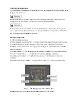
Page 17: ...r KPD100 intelligent controller fig 3 11 is installed on the ATS cabinet ATS switching is controlled by KPD100 intelligent controller obtaining the built in ATS controlling function with default insta...

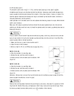
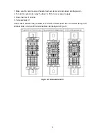
Page 18: ...ause serious personal injury or even death Do not try to manually operate switches when there is load Cut off both the power supplies before manual operation 1 Make sure there is no load on the transf...

Page 19: ...n to auto mode relay the fuse F2 F5 to recover power supply 3 Close the door of cabinet C Terminal block X1 Control cable between the generator set and ATS cabinet needs to be connected through the te...

Page 20: ...ponents Surge protector SPD Surge protecting system applies combined SPD which is composed of voltage switching type component and voltage limiting type component The protection mode can be optional d...

Page 21: ...or gas or the relevant ventilation area for emission 3 4 3 Mounting method ATS cabinet can be mounted vertical or on the wall Wall mounting Small or medium sized ATS cabinet 40A 400A can be mounted on...

Page 22: ...mounting may cause the equipment failure or damage Pay special attention not to have the drilling debris or filings into ATS connection terminal block contactor or other parts Additionally pay attent...

Page 23: ...have been cut off Fig 3 15 Terminal arrangement of 200A two pole transfer switch inc 100A transfer switch Fig 3 16 Terminal arrangement of 40 200A four pole transfer switch inc 50A 75A 100A 125A 160A...

Page 24: ...250 400A four pole transfer switch inc 320A transfer switch similar for three pole Fig 3 18 Terminal arrangement of 630 1600A four pole transfer switch inc 800A 1250A transfer switch Control connecti...

Page 25: ...6 Both the terminals of quick connection type quick connector control cable section area 1 0m The length can be optional according to the onsite installation location with recommended value 15m are re...

Page 26: ...atures 1 control protection function Realize the function of generator manual or automatic starting stopping ATS transfer and alarm protection 2 12 24VDC power supply 3 manual and automatic working mo...

Page 27: ...o set the generator to be under AUTO mode Press this key to increase parameters when at Parameter set mode equal to Manual par ameter saving key The key is to set the generator to be under MAN mode Pr...

Page 28: ...Unit Pre setti ng Value Description ReStart Cnt Time s 3 Fixed parameter unchangeable Time lag of grid returning to be normal Sec 30 Can be set as 0s 5s 10s 20s 30s 60s 180s Time lag of generator pre...

Page 29: ...test run under manual mode has been finished Trial run at automatic mode A Turn on the power switch it enters into Manual mode automatically Press the key It enter into auto mode the auto indicator l...

Page 30: ...ontrol panel will be light Controller will monitor the grid data See the following table When the data goes to be continuously abnormal controller will start the generator set and make ATS cabinet swi...

Page 31: ...f it is equipped with C Then disconnect the starting battery Disconnect pole first 2 Clean A Clean all controller gages switches and inner bus and connection chips by a vacuum cleaner B Close the case...

Page 32: ...arest KIPOR dealer if maintenance is required Maintenance personnel will service you at any moment For Chinese customers please contact Tel xxxxxxxxx Fax xxxxxxxxx Service support Please offer the spe...

Page 33: ...pipes fault 2 Electronic speed regulator or line fault 3 Electronic speed regulator s abnormal signal lead to no output 4 Actuator fault 1 Check the fuel level and ensure no air in the fuel pipes filt...

Page 34: ...1 Wiring fault 2 F2 fuse on the terminal strip X1 melts down 3 Inner contactors of KPD100 controller terminal 34 35 are open 4 Transfer switch broken 1 Check wiring between ATS and generator 2 Check...

Page 35: ...e 110V 120V Single phase 220V 240V Three phase three wire 110 190V Three phase three wire 115 200V Three phase three wire 120 208V Three phase three wire 127 220V Three phase three wire 133 230V Three...

Page 36: ...abinet IP32 Indoor IP54 Outdoor cabinet Control type Battery voltage 12V 24V Battery charger 12V 4A 24V 4A Options Surge protection device SPD Surge protection device Remote control plug socket of ATS...

Page 37: ...ed repair will not be given for the followings z Aging after use for some time natural fading of coating surface and metal plating z Normal sense without influencing quality and performance noise vibr...

Page 38: ...6 Attachment 1 Electric principle figure four figures together...

Page 39: ......

Page 40: ...2 User wiring diagram six together...

Page 41: ......

Page 42: ......

Page 43: ...3 Definition of ATS cabinet remote control aviation plug option...

Page 44: ...ngyi Road Beside Three Period Industry Kit Park Wangzhuang National High and New Technique Industry Development Area Wuxi Tel 0510 85205100 0510 85203799 Fax 0510 85205026 0510 85203795 E MAIL kipor k...

Reviews: