16-10-200716-10-2007
MKIV OPERATOR’S MANUAL
99
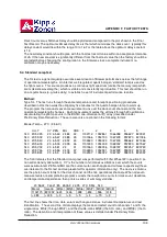
866 4 16883 8442 869.5
876 5 27775 12421 879.5
887 7 40973 15486 891.5
897 6 55779 22772 901.6
908 10 71077 22477 911.6
918 9 86191 28730 923.6
929 8 99579 35206 933.6
939 17 111900 27140 943.7
950 9 122532 40844 955.7
960 11 131484 39644 965.7
971 14 138978 37143 975.7
981 18 144932 34161 985.7
992 17 149962 36371 995.8
1002 15 153943 39748 1007.8
1013 18 157825 37200 1017.8
1023 19 160926 36919 1027.8
1034 19 163407 37488 1037.9
1044 22 165796 35348 1049.9
1055 19 168082 38561 1059.9
1065 24 170292 34761 1069.9
1076 25 172626 34525 1082.0
1086 26 175036 34327 1092.0
1097 29 177199 32905 1102.0
6.
A plot of the dark count and wavelength 1 intensity values vs the high voltage should be
compared to the plot in the Final Test Record.
The wavelength 1 data should exhibit a region of minimum slope (plateau).
The optimum setting for the high voltage is at the beginning of the plateau. The ratio is
determined by deviding the counts of wavelength 1 by the square root of the dark count.
If the new established optimum high voltage value deviates approximately 50 Volts or more
from the orignial setting then it is desired to change the current setting. See the HVSET
explanation on how to adjust the high voltage.
WARNING:
Changing the high voltage for the photomuliplier may effect the ozon
calibration, but will change the UV calibration for sure. The best time for
adjusting the high voltage is therefore during re-calibration of the Brewer
instrument.
HVSET: Set PMT High Voltage
HVSET is used to set the PMT High Voltage as determined from the HV test.
This test requires access to the High voltage module and the front of the Main Electronics Circuit
Board.
Prior to starting the test, locate shorting plug J2 and potentiometer R4 on the High Voltage Module,
and test point E16 on the Main Electronics Board.
Method
:
1. If not already done so, then turn off Brewer power and on the high voltage module move jumper
J2 from Pins 2-3 to Pins 1-2, and restore Brewer power.
2. Enter the
HVSET
command and enter the desired HV value at the prompt.
3. Measure the voltage at E16 on the Main Electronics PCB and write the value down.
4. Turn off Brewer power and set jumper J2 back to pins 2-3, and restore power.
5. Monitor E16 and adjust R4 on the High Voltage Module until E16 is set to the voltage as recorded
in step 3.
6. Confirm the setting with an AP command.
APPENDIX F FACTORY TESTS
Summary of Contents for BREWER MK IV
Page 1: ...INSTRUCTION MANUAL OM BA C230 B Mk IV...
Page 2: ...REVISION HISTORY REV DESCRIPTION DCN DATE APPD B Update 99 16 12 C Update 07 16 10...
Page 3: ...ii...
Page 5: ...2...
Page 7: ...4...
Page 25: ...MKIV OPERATOR S MANUAL 22...
Page 57: ...MKIV OPERATOR S MANUAL 54...
Page 61: ...MKIV OPERATOR S MANUAL 58...
Page 81: ...MKIV OPERATOR S MANUAL 78...
Page 91: ...MKIV OPERATOR S MANUAL 88...
Page 93: ...MKIV OPERATOR S MANUAL 90...
Page 127: ...MKIV OPERATOR S MANUAL 124...
Page 133: ...MKIV OPERATOR S MANUAL 130...
Page 135: ...MKIV OPERATOR S MANUAL 132...

