MKIV OPERATOR'S MANUAL
104
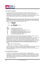
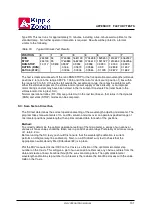
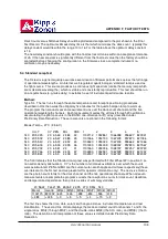
The third line of data shows the standard deviation for each of the quantities in the line above (there
is no ASCII symbol for '±', hence the leading '+' sign).
The single-ratios MS(4) through MS(7) should remain reasonably constant from test to test; the
allowable drifts in the SO
2
(MS(8)) and O
3
(MS(9)) double-ratios are about ±1.5%.
SR: Azimuth Tracker Steps-per-Revolution Calibration
The SR test determines the number of steps required for the azimuth drive motor to turn the Brewer
through 360
°
in azimuth. This test establishes the steps-per-revolution constant which is used by
the Brewer program to orient the Brewer in azimuth to within ±1 minute of arc.
An opto-sensor located inside the Azimuth Tracker detects a reference flange on the stationary
drive-wheel. The azimuth drive motor is 'zeroed' on this reference, then stepped forward until the
flange is again detected on the next revolution. At this point the tracker has rotated exactly 360
°
,
and the steps-per-revolution constant has been determined.
The SR routine can only be accessed if the instrument configuration (IC) has been setup to include
an Azimuth Tracker.
Method:
Type SR to initiate the steps-per-revolution test. The first portion of the calibration proceeds exactly
as for AZ . Once the internal optically-sensed reference flange has been detected, the azimuth
step-count is set to zero and the drive motor is stepped forward until the flange is again detected
after 360
°
of rotation.
It takes approximately 30 seconds to rotate through 360
°
.
The discrepancy between the saved value and the new value will be displayed. If this value is
greater then 20 steps the tracker's friction drive should be cleaned and the test should be repeated.
If the discrepancy persists the azimuth steps per revolution value in the instrument configuration
value should be changed to the new value.
Afetr this test the Azimuth Tracker will return to the solar azimuth and the previously displayed menu
will appear.
Stray Light Measurement
Stray light is radiation measured by the Brewer that has a wavelength that should not be found in
the the Brewer. If the entrance slit of the Brewer is illuminated only with radiation of 325nm all
radiation of other wavelengths measured in the Brewer is stray light. Stray light causes small errors
in the Brewer’s UV reading because some light of an incorrect wavelength is measured. The
amount of stray light expected in a Brewer is defined by its stray light rejection (R). R is defined as
the ratio of the peak intensity to the background intensity measured while the UV dome is uniformly
illuminated by the 325nm beam of a HeCd laser.
Method:
The peak is found by fitting a line to both sides of the peak (using method of least squares) and
calculating the point of intersection between the two lines. The max. intensity value is discarded (as
it is not known whether it will be on the upward or downward slope) and the 5 points to either side
are used to calculate the best fit lines. The lines fit almost exactly and the peak is found very
precisely as the statistical error is typically about 0.1%.
The background is the average of the intensities for wavelengths between 2870A and 3220A.
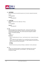
The following equations are used to evaluate stray light.
Summary of Contents for BREWER MK IV
Page 1: ...INSTRUCTION MANUAL OM BA C230 B Mk IV...
Page 2: ...REVISION HISTORY REV DESCRIPTION DCN DATE APPD B Update 99 16 12 C Update 07 16 10...
Page 3: ...ii...
Page 5: ...2...
Page 7: ...4...
Page 25: ...MKIV OPERATOR S MANUAL 22...
Page 57: ...MKIV OPERATOR S MANUAL 54...
Page 61: ...MKIV OPERATOR S MANUAL 58...
Page 81: ...MKIV OPERATOR S MANUAL 78...
Page 91: ...MKIV OPERATOR S MANUAL 88...
Page 93: ...MKIV OPERATOR S MANUAL 90...
Page 127: ...MKIV OPERATOR S MANUAL 124...
Page 133: ...MKIV OPERATOR S MANUAL 130...
Page 135: ...MKIV OPERATOR S MANUAL 132...


