17
8.9
Connecting a SMART sensor via RS-485
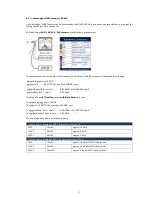
Up to 8 Modbus® SMART sensors can be addressed by the LOGBOX SE. Each one needs a unique address. Instructions for
setting the address are in section 10.9
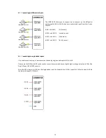
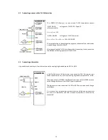
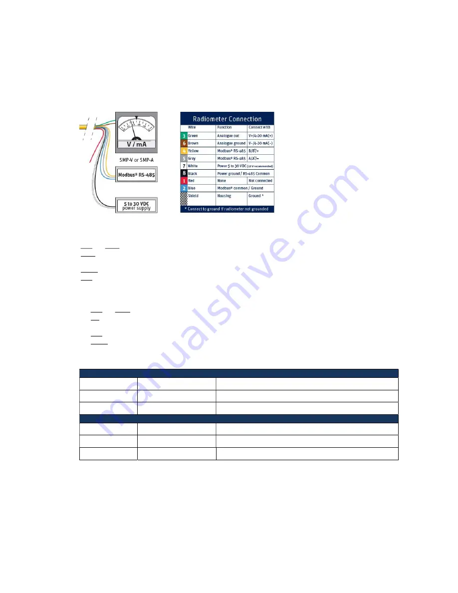
All Kipp & Zonen
SMP- SGR- SUV - SHP sensors
have the following connections:
The sensors need constant power to stabilise and to be able to provide fast response to irradiation level changes.
blue and black wire(s)
GND
white wire(s)
BATTOUT or parallel to POWER input
yellow Modbus® B/B’/+ wire(s)
RS-485B+ on LOGBOX SE board
grey Modbus® A/A’/- wire(s)
RS-485A-
“”
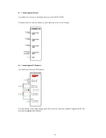
The Kipp & Zonen
RT1 rooftop
sensor
with black data
cable uses:
The blue and green wire(s)
GND
The red wire
BATTOUT or parallel to POWER input
The grey Modbus® Data + wire(s)
RS-485B+ on LOGBOX SE board
The yellow Modbus® Data - wire(s)
RS-485A
-
“”
All remaining wires need to be isolated properly.
Typical power consumption SMP-V for maximum output (1 V)
5 VDC
50 mW
approx. 10.0 mA
12 VDC
55 mW
approx. 4.5 mA
24 VDC
60 mW
approx. 2.5 mA
Typical power consumption SMP-A for maximum output (20mA)
5 VDC
77 mW
approx. 28 mA with 100Ω load resistor
12 VDC
83 mW
approx. 24 mA with 100Ω load resistor
24 VDC
100 mW
approx. 6 mA with 100 Ω load resistor

