The following sections provide information on the installation of the SOLYS. The installation will be explained step by step in this
chapter. A video of the SOLYS installation can be found on the product page of the SOLYS on our website.
Apart from the creation of the SOLYS Tripod Floor Stand support base and the assembling of the accessories and instruments, the
leveling and the fine adjustment is only a matter of minutes. However a clear sun is required to do this adjustment. It is important
that these steps are carried out in the right order.
2.1 Tools required for SOLYS installation
For installation on site the following materials are included with the SOLYS.
• Allen Wrench key type 6 (for M8 bolts for tripod)
• Allen Wrench key type 3
• Allen Wrench key type 2.5
• Screws M8 x 20 plus M8 washers
Required but not included:
• Screwdriver for connection of power cable to the connector
• Cable for power connection of the SOLYS
• Compass to find geographical East
2.1.1 Tools required for shading ball assembly / sun sensor
The tools required for mounting the shading ball assembly are included.
Required but not included: A ruler, to measure the position of the sun sensor.
2.1.2 Site preparation
A site must be prepared before installing a SOLYS sun tracker. The following points need to checked.
The site where the SOLYS sun tracker is placed must be free of obstructions. In order to have a free 360 degree field of view for the
SOLYS sensors (see also pyranometer instruction sheets for details).
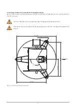
Building a concrete or steel horizontal platform for mounting the SOLYS tripod. The SOLYS tripod dimensions are given in this
manual. A solid stable base is essential for accurate tracking.
Provide power connection for the SOLYS (either 115 to 230 VAC or 24 VDC). The SOLYS has power connectors included for both VDC
and VAC (no cable supplied). Because the SOLYS is rotating the SOLYS user needs to purchase a flexible cable. Cable specifications
are given in this manual. If both 24 VDC and 115 to 230 VAC are supplied the SOLYS will use the VAC power until this is cut off. The
SOLYS will then switch to VDC without interruption.
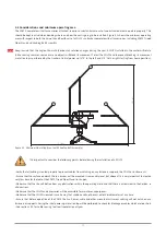
If a meteorological mast is placed near the SOLYS, make sure the position is such that the location of the mast is between the
SOLYS and the nearest pole (North- or South pole). In this way the mast will never block the direct radiation. A rule of thumb is
that the distance between a mast with height ‘h’ and the SOLYS should be at least 10 times ‘h’.
2. Installation
13
Summary of Contents for SOLYS Gear Drive
Page 1: ...SOLYS2 Sun Tracker SOLYS Gear Drive Sun Tracker Instruction Manual...
Page 2: ...2...
Page 4: ...4...
Page 6: ...6...
Page 10: ...10...
Page 39: ...Figure 3 13 Adjustment of the sun sensor 21 0 5 mm 3x 39...
Page 61: ...6 Insert the Ethernet cable Contacts on this side 61...
Page 78: ...78...
Page 80: ...80...
Page 86: ...86...
Page 88: ...88...
Page 112: ......


