background image

DE

EN

FR ES

H E I N R I C H   K I P P   W E R K

H E I N R I C H   K I P P   W E R K

www.kipp.com

export@kipp.com

Tel. +49 7454 793-0

OPERATING INSTRUCTIONS

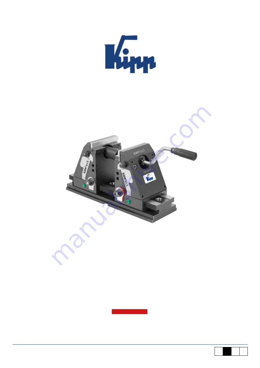
KIPPflexX 5-axis vice

Edition 2022

Summary of Contents for KIPPflexX K1555

Page 1: ...DE EN FR ES H E I N R I C H K I P P W E R K H E I N R I C H K I P P W E R K www kipp com export kipp com Tel 49 7454 793 0 OPERATING INSTRUCTIONS KIPPflexX 5 axis vice Edition 2022 ...

Page 2: ......

Page 3: ...tion of the difference between positive down force clamping and normal clamping 3 3 Mounting and positioning possibilities of the baseplate 3 4 Clamp construction sequence for vice normal clamping 3 5 Clamp construction sequence for positive down force clamping 3 6 Match the clamping shaft to the workpiece length 3 7 Technical data 3 8 Accessories 3 9 Exchanging the jaw plates 4 Care and maintenan...

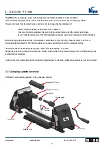
Page 4: ...onstructed according to the latest technology including all relevant safety regulations The clamping system is to be used exclusively for holding workpieces that are machined on milling machines This KIPPflexX 5 axis clamping system may only be used if all safety devices of the machine are absolutely functional The KIPPflexX 5 axis clamping system can cause serious material damage if it is operate...

Page 5: ...iece may only have a maximum parallel displacement of 0 5mm along the entire clamping width K0946 pin with Ø 6mm cup point universal pin for positive clamping without pre embossing e g machining blanks The spindle nut may not be moved beyond the marking V notch on the shaft This ensures that a sufficient number of threads is always used The union nut must contact the face of the extension shaft be...

Page 6: ...this jaw can be moved and clamps using the normal vice principle see 3 2 Technical explanation of the difference between positive down force clamping and normal clamping When using the positive down function the workpiece is pulled down onto the rest with a repeat accuracy of 0 01mm A workpiece clamping height of 155 180mm enables very good accessibility with short tools when machining The clampin...

Page 7: ... 60 mm Extension rod 60 mm Extension rod 120 mm Adapter shaft 180 mm Adapter shaft 60 mm Adapter shaft 120 mm Spindle nut Jaw unit left Jaw unit right Baseplate L 400 Threaded spindle Crank Ring bolt for lifting www kipp com export kipp com Tel 49 7454 793 0 KIPPflexX 5 axis clamping system L 630 package contents 3 D E S C R I P T I O N KIPPflexX 5 axis clamping system L 400 package contents ...

Page 8: ... Torque wrench Pivot point Pivot point Locating and support element Locating and support element Clamping element Clamping element Positive down force Repeat accuracy 0 01 mm clamped Support accuracy Clamping element Support accuracy Symmetry Locating and support element Thrust piece pre centring Thrust piece pre centring Symmetry Symmetry www kipp com export kipp com Tel 49 7454 793 0 3 2 Technic...

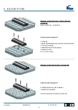
Page 9: ...6 Clamping claw set K1008 consisting of 4x claw clamps M12 or M16 4x T slot nuts M12 or M16 4x cap screws M12 or M16 4x washers M12 or M16 Optional 2x slot guide keys for 14mm or 18mm T slots 2x M6x12 fastening screws for slot guide keys Base plate on pallet with T slots machine table 3x M12x65 cap screws through the baseplate Positioning and fastening with 2x T slot keys 14 or 18 mm 2x M6x12 fast...

Page 10: ...e There are 3 reamed holes for available for a 50mm grid Baseplate on pallet with T slots machine table with central bore over a central bolt 1x slot guide key Positioning and fastening with 1x central bolt customer specific depending on the central bore in the machine table 1x 14 18mm slot guide key 1x M6x12 fastening screw for slot guide key 3x M12x65 cap screws 3x 14 or 18mm T slot nuts 3 D E S...

Page 11: ...ng pin 1x clamping pin form B for 25 H7 bores collar height 5mm for M12 cap screw compensating bayonet pin The clamping pins are screwed into the baseplate using M12 screws The centring in the baseplate takes place via 2x Ø25H7 bores whereby the clamping pins are positioned with repeat accuracy Bottom view of the baseplate with mounted zero point clamping pins 3 D E S C R I P T I O N ...

Page 12: ...o point clamping system 52 gauge 8x clamping bolts can be screwed to the baseplate from below Fit diameter Ø12H6 thread M8 gauge 52mm The clamping bolt is screwed to the baseplate using M8 screws The centring in the baseplate takes place via 8x Ø12H6 bores whereby the clamping pins are positioned with repeat accuracy ...

Page 13: ... point clamping system 96 gauge 8x clamping bolts can be screwed to the baseplate from below Fit diameter Ø16H6 thread M10 gauge 96mm The clamping bolt is screwed to the baseplate using M10 screws The centring in the baseplate takes place via 8x Ø16H6 bores whereby the clamping pins are positioned with repeat accuracy ...

Page 14: ...to the desired position Ensure that the clamping elements do not protrude into the T slot of the jaw unit otherwise they may jam in the baseplate when pushed on The desired workpiece size and required adapter shafts can be read off using the symbols and scale and set on the base plate This enables a quick pre positioning of the jaw unit in the desired clamping range 3 D E S C R I P T I O N ...

Page 15: ...ned no red marking should be visible Pre centre the jaw unit via thrust pins shown in green by pushing into the toothing Now tighten the nut on the clamping element shown in blue using a torque wrench set to min 50Nm max 100Nm until the red marking is no longer visible The jaw unit is now completely positively engaged with the baseplate through the toothing Thrust pad Clamping element 3 D E S C R ...

Page 16: ...s open onto the baseplate Pre set the threaded spindle with the corresponding adapter shaft on the movable locking pin shown in brown before mounting on the vice The clamping shaft is later hung onto the fixed locking pin shown in pink By presetting with the locking pins a quick assembly of the threaded spindle incl adapter shaft is achieved 3 D E S C R I P T I O N ...

Page 17: ...th corresponding adapter shaft This can be done from both sides Then insert into the fixed locking pin shown in pink at the back Secure the indexing plunger shown in brown by turning it clockwise into the hole shown in pink of the threaded spindle and adapter shaft 3 D E S C R I P T I O N ...

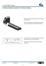
Page 18: ...ns This type of mounting enables the KIPPflexX 5 axis clamping system to be used as a normal vice Use the crank handle to move the right hand jaw unit to the appropriate clamping width The jaw unit can be infinitely adjusted through 60 mm via the threaded spindle The torque wrench K1489 01 is recommended for tightening 3 D E S C R I P T I O N ...

Page 19: ...positive down vice the following must then be observed Preset the KIPPflexX 5 axis clamping system using the crank handle Example A workpiece is 145mm long To create a pull down effect a maximum of 2mm must be added to the actual workpiece length here max 147mm Follow all the previous steps carried out for the normal vice version 3 D E S C R I P T I O N ...

Page 20: ...0 Lay the workpiece in and position it against the fixed jaw unit here left Pre centre the clamping unit in the toothing using the thrust piece shown in green Then tighten the clamping piece shown in blue with the nut min 50 Nm max 100 Nm 3 D E S C R I P T I O N ...

Page 21: ...mping elements is no longer visible and produces a form fit on the baseplate with the toothing This type of mounting enables the KIPPflexX 5 axis clamping system to be used as a positive down force vice The KIPP torque wrench K1489 01 is recommended for tightening 3 D E S C R I P T I O N ...

Page 22: ...28 78mm Adapter shaft 60mm Threaded spindle Clamping width 76 5 146mm Adapter shaft 120mm Threaded spindle Clamping width overview base plate L 280 mm Clamping width up to 180mm Adapter shaft 180mm Threaded spindle Accessories 3 D E S C R I P T I O N 3 6 Match the clamping shaft to the workpiece length ...

Page 23: ...om Tel 49 7454 793 0 Clamping width 28 78mm Adapter shaft 60mm Threaded spindle Clamping width 76 5 146mm Adapter shaft 120mm Threaded spindle Clamping width overview base plate L 400 mm Clamping width 136 5 206mm Adapter shaft 180mm Threaded spindle 3 D E S C R I P T I O N ...

Page 24: ...Adapter shaft 180mm Extension shaft 120mm Extension shaft 240mm Threaded spindle For wider clamping widths beyond the crank range the 120mm extension shaft accessory can be added Clamping width up to 780mm Additional baseplate L 400mm Adapter shaft 180mm Extension shaft 120mm Extension shaft 480mm Threaded spindle An infinite clamping range is achieved using a combination of 60 120 240 480mm exten...

Page 25: ...8mm Adapter shaft 60mm Threaded spindle Clamping width 76 5 146mm Adapter shaft 120mm Threaded spindle Clamping width overview base plate L 630 mm Clamping width 136 5 206mm Adapter shaft 180mm Threaded spindle Clamping width up to 206mm Adapter shaft 180mm Extension shaft 60 mm Threaded spindle 3 D E S C R I P T I O N ...

Page 26: ...Adapter shaft 180mm Extension shaft 120 mm Extension shaft 60 mm Threaded spindle Clamping width up to 426mm Adapter shaft 180mm Extension shaft 120 mm Extension shaft 60 mm Extension shaft 60 mm Threaded spindle Clamping width up to 526mm Adapter shaft 180mm Extension shaft 120 mm Extension shaft 60 mm Extension shaft 60 mm Extension shaft 120 mm Threaded spindle Accessories 3 D E S C R I P T I O...

Page 27: ...vel the force is greater For maximum force with the positive down function a tightening force of 140Nm can be used General information The values shown for the normal vice and positive down effect refer to the force applied directly to the workpiece 3 D E S C R I P T I O N Other lengths on request Jaw width 90 mm 125 mm Baseplate length L 280 mm L 400 mm L 280 mm L 400 mm L 630 mm Clamping height ...

Page 28: ...on our homepage Jaw plates smooth K1557 supplied singly Jaw plates with pins K1557 supplied singly Combination jaw plates smooth and with pins K1557 supplied singly Seating ledges K0974 supplied in pairs Available in H 12mm 17mm Seating ledges screw on K0974 to mill to size supplied in pairs Jaw plates machinable K0975 supplied singly Extension shafts K0990 Available in L 120mm 240mm 480 mm Cylind...

Page 29: ...e that only the ball of the spring plunger 13 is projecting from the back of the stop arm 10 Only tighten the swivel screw 11 where required so much so that the stop can still swivel Secure the screw 11 against loosening with the spring washer 14 The spring washer 14 pre tensions the stop The centring ring 12 guides the stop Slide the stop pin 15 into position and clamp with the cap screw 16 3 D E...

Page 30: ...ng that the 2 O rings 20 are not damaged or misplaced Remove rear clamping element 21 from the jaw by lifting diagonally upwards Screw out the 2 M6x10 Torx screws Exchange the jaw plate 18 To re assemble follow the previous instructions in reverse Only tighten the screw 19 hand tight 3 D E S C R I P T I O N 18 Jaw plate 90 mm 125 mm 19 Shoulder screws similar to DIN ISO 7379 Ø8x40 M6 Ø10x40 M8 20 ...

Page 31: ...KIPP WERK GmbH Co KG is prohibited HEINRICH KIPP WERK GmbH Co KG continuously develops its products in compliance with its own policy HEINRICH KIPP WERK GmbH Co KG reserves the right to make changes and improvements to any of the products described in this document without prior notice HEINRICH KIPP WERK GmbH Co KG is under no circumstances responsible for any type of special incidental consequent...

Page 32: ......

Reviews: