9
VISION 1460 INSTALL GUIDE
4-wire harness
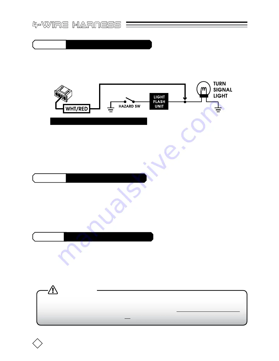
This input connects to the vehicle’s Hazard (turn signal) lights and works in
combination with the door lock and unlock inputs to inform the 1460 when
to Arm/Disarm. See
Fig-3
below.
Connect the WHT/RED wire as shown in
Fig-3
above (also shown on the
next page),
between the vehicle’s Light Flash Unit and the turn signal light.
The correct wire should show +12v when the turn signal light is illuminated.
WHT/RED
(+)12v Hazard Light Input
This input normally connects to the Unlock wire between the “door lock re-
lay control module” and the vehicle’s door lock actuator motors
(see page 10)
.
This input is vital for the 1460 to know when to Arm/Disarm.
BLU/YEL
(+)12v Door UNLOCK Input
GRN/YEL
(+)12v Door LOCK Input
This input normally connects to the Lock wire between the “door lock relay
control module” and the vehicle’s door lock actuator motors
(see page 10)
.
This input is vital for the 1460 to know when to Arm/Disarm.
FIG-3: Connecting the Hazard Light Input
All 3 connections on this page are very important.
Connecting them
incorrectly will result in malfunction of the 1460. NEVER use electrotaps!
Only use
PosiTap
connectors or
solder
.
WARNING!


