FP520 Service Manual
Page 19 of 64
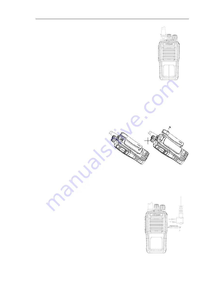
5.2 Installing/Removing the Antenna (see Fig. 20)
When installing, put the antenna end with screw thread into the threaded hole of the
radio top, and turn it clockwise until it is fastened.
For the removing, hold the antenna bottom and turn it counterclockwise.
Fig. 20
5.3 Installing/Removing the Belt Clip (see Fig.21)
When installing, align the screw holes of the belt clip with the corresponding ones of the radio back shell, and
use two 2.5x8.0 machine screws to fasten.
Loosen the two 2.5x8.0 machine screws to detach the belt clip.
Fig. 21
5.4 Installing the Earphone (see Fig. 22)
When the earphone is needed, open the earphone cover on the upper right
side of the radio, and put the earphone plug into the interface.
Fig. 22
Summary of Contents for FP520
Page 1: ... 键入文档副标题 gh 选取日期 在此处键入文档的摘要 摘要通常是对文档内容的简短总结 在此处键入文档的摘要 摘要 通常是对文档内容的简短总结 ...
Page 44: ...FP520 Service Manual Page 43 of 64 Figure 1 FP520 01 Mainboard Schematic Diagram 136 174MHz ...
Page 45: ...FP520 Service Manual Page 44 of 64 ...
Page 46: ...FP520 Service Manual Page 45 of 64 ...
Page 47: ...FP520 Service Manual Page 46 of 64 ...
Page 48: ...FP520 Service Manual Page 47 of 64 ...
Page 49: ...FP520 Service Manual Page 48 of 64 ...
Page 50: ...FP520 Service Manual Page 49 of 64 ...
Page 51: ...FP520 Service Manual Page 50 of 64 ...
Page 54: ...FP520 Service Manual Page 53 of 64 Figure 4 FP520 02 Mainboard Schematic Diagram 400 470MHz ...
Page 55: ...FP520 Service Manual Page 54 of 64 ...
Page 56: ...FP520 Service Manual Page 55 of 64 ...
Page 57: ...FP520 Service Manual Page 56 of 64 ...
Page 58: ...FP520 Service Manual Page 57 of 64 ...
Page 59: ...FP520 Service Manual Page 58 of 64 ...
Page 60: ...FP520 Service Manual Page 59 of 64 ...
Page 61: ...FP520 Service Manual Page 60 of 64 ...
Page 64: ...FP520 Service Manual Page 63 of 64 Figure 7 KBC 51 7 4V Electrical Schematic Diagram ...


