FP520 Service Manual
Page 20 of 64
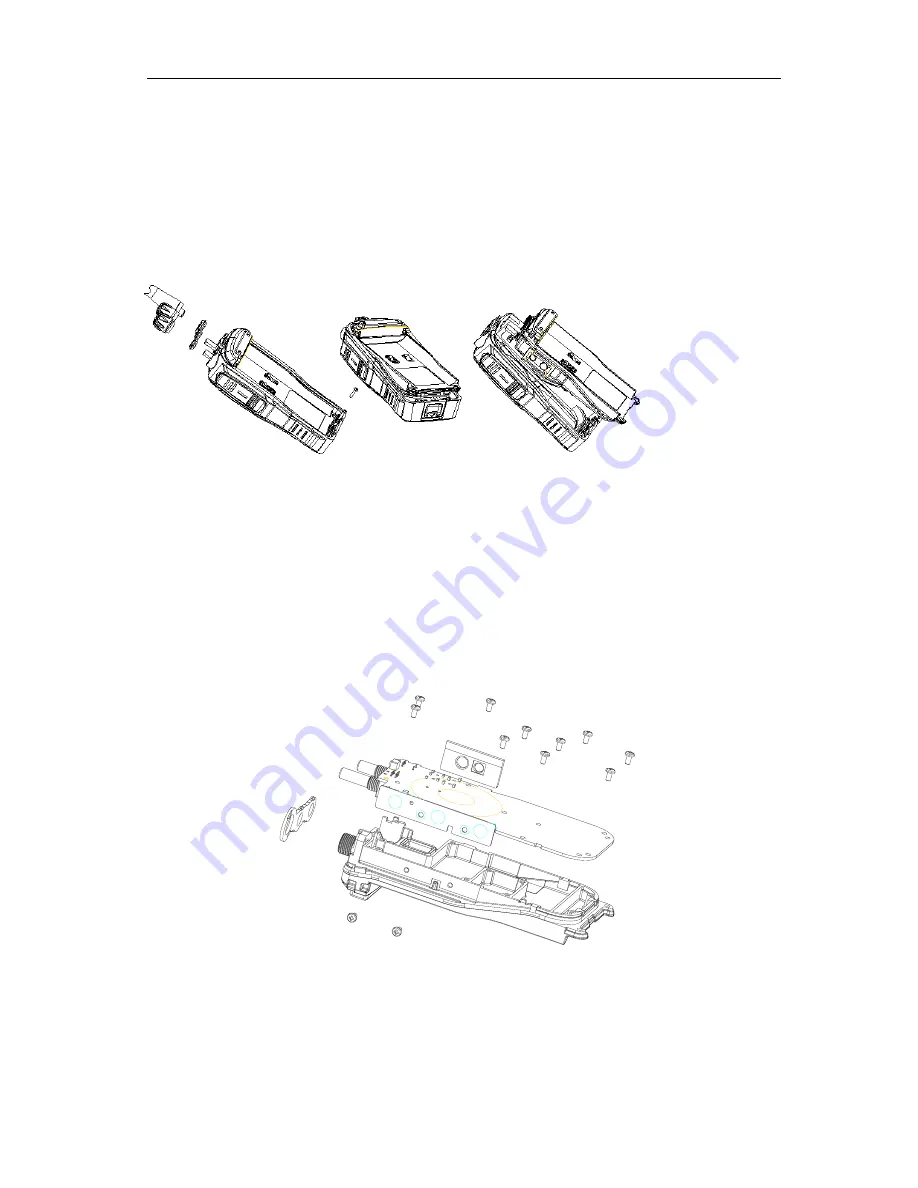
5.5 Separating the Front Cover from the Chassis (see Fig. 23)
1. Removing the antenna, volume knob and channel knob;
2. Removing the two knob nuts and one antenna nut;
3. Removing the two aluminum screws with wabblers;
4. Use a pair of tweezers or other tools to lever open the bottom;
5. Pull out the Front Cover;
6. Use an electric soldering iron to cut off the speaker wire and MIC wire, and the separation is done.
Fig. 23
5.6 Separating the PCB Board from the Chassis (See Fig. 24)
1. Remove the potentiometer waterproof pad on top;
2. Remove the earphone waterproof plug;
3. Remove the screws on the PCB mainboard;
4. Remove the two screws on the side PTT PCB;
5. Use an electric soldering iron to cut off the antenna terminal and the PCB board is removed. (PTT PCB is
connected with the PCB mainboard. To avoid bonding pad damage, use an electric soldering iron to separate
them instead of dividing them with force)
Fig. 24
After the disassembly above is completed, the repair and adjustment can then be done.
5.7 Exploded View
Summary of Contents for FP520
Page 1: ... 键入文档副标题 gh 选取日期 在此处键入文档的摘要 摘要通常是对文档内容的简短总结 在此处键入文档的摘要 摘要 通常是对文档内容的简短总结 ...
Page 44: ...FP520 Service Manual Page 43 of 64 Figure 1 FP520 01 Mainboard Schematic Diagram 136 174MHz ...
Page 45: ...FP520 Service Manual Page 44 of 64 ...
Page 46: ...FP520 Service Manual Page 45 of 64 ...
Page 47: ...FP520 Service Manual Page 46 of 64 ...
Page 48: ...FP520 Service Manual Page 47 of 64 ...
Page 49: ...FP520 Service Manual Page 48 of 64 ...
Page 50: ...FP520 Service Manual Page 49 of 64 ...
Page 51: ...FP520 Service Manual Page 50 of 64 ...
Page 54: ...FP520 Service Manual Page 53 of 64 Figure 4 FP520 02 Mainboard Schematic Diagram 400 470MHz ...
Page 55: ...FP520 Service Manual Page 54 of 64 ...
Page 56: ...FP520 Service Manual Page 55 of 64 ...
Page 57: ...FP520 Service Manual Page 56 of 64 ...
Page 58: ...FP520 Service Manual Page 57 of 64 ...
Page 59: ...FP520 Service Manual Page 58 of 64 ...
Page 60: ...FP520 Service Manual Page 59 of 64 ...
Page 61: ...FP520 Service Manual Page 60 of 64 ...
Page 64: ...FP520 Service Manual Page 63 of 64 Figure 7 KBC 51 7 4V Electrical Schematic Diagram ...


