FP520 Service Manual
Page 21 of 64
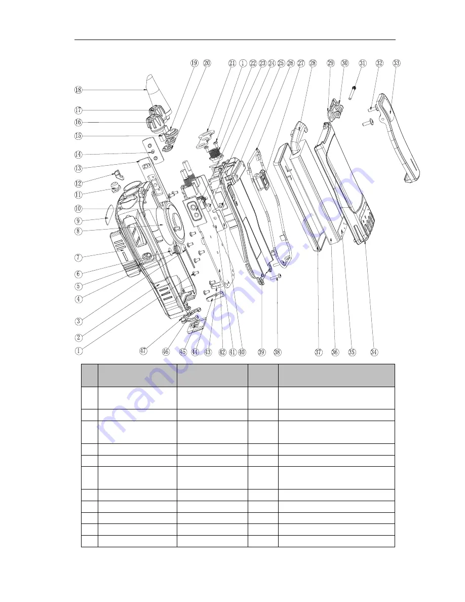
No
.
Part no.
Description
Quantity
Remark
1
7SMF-020040M-SZYB-N
M2*4 round flat head
machine screw
13
fixes the PCB board, PTT button and
antenna screw
2
7MHP-4083-01A-W0
FP520 front cover
1
ABS+PC;black;silk screen/texturing
3
4SM7-6027-A40C
MIC microphone
1
Φ6.0, -40±2dB omnidirectional,2.2KΩ,2V,
with 80mm red black wire
4
7MHR-1727-09A-W3
microphone cover
1
Silica gel, hardness 40, orange
5
7MHP-7208-06A-W0
earphone cover plug
1
ABS+PC;black;texturing
6
7GCB-070001
microphone waterproof
cloth
1
waterproof cloth, diameter
φ7mm,
thickness 0.1mm
7
7MHP-7208-07A-W0
earphone cover
1
TPU;black
8
7GCB-360001-W0
speaker waterproof net
1
Black
, φ36
9
7PLJ-4083-E01A
LOGO sticker
1
T=0.3mm PC
10
4SS7-4050-016-100
speaker
1
MM4050-
1638,16Ω,1W,
∅
40
11
7MHR-7208-05A-W3
emergency button
1
silica gel; orange
Summary of Contents for FP520
Page 1: ... 键入文档副标题 gh 选取日期 在此处键入文档的摘要 摘要通常是对文档内容的简短总结 在此处键入文档的摘要 摘要 通常是对文档内容的简短总结 ...
Page 44: ...FP520 Service Manual Page 43 of 64 Figure 1 FP520 01 Mainboard Schematic Diagram 136 174MHz ...
Page 45: ...FP520 Service Manual Page 44 of 64 ...
Page 46: ...FP520 Service Manual Page 45 of 64 ...
Page 47: ...FP520 Service Manual Page 46 of 64 ...
Page 48: ...FP520 Service Manual Page 47 of 64 ...
Page 49: ...FP520 Service Manual Page 48 of 64 ...
Page 50: ...FP520 Service Manual Page 49 of 64 ...
Page 51: ...FP520 Service Manual Page 50 of 64 ...
Page 54: ...FP520 Service Manual Page 53 of 64 Figure 4 FP520 02 Mainboard Schematic Diagram 400 470MHz ...
Page 55: ...FP520 Service Manual Page 54 of 64 ...
Page 56: ...FP520 Service Manual Page 55 of 64 ...
Page 57: ...FP520 Service Manual Page 56 of 64 ...
Page 58: ...FP520 Service Manual Page 57 of 64 ...
Page 59: ...FP520 Service Manual Page 58 of 64 ...
Page 60: ...FP520 Service Manual Page 59 of 64 ...
Page 61: ...FP520 Service Manual Page 60 of 64 ...
Page 64: ...FP520 Service Manual Page 63 of 64 Figure 7 KBC 51 7 4V Electrical Schematic Diagram ...


