PT568 Service Manual
13
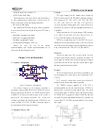
Figure 6.1 External Speaker/Microphone Interface Definition
6.2 Adjustment
After changing components during the maintenance, it is
necessary to test the radio and adjust its technical parameters. The
following part is going to introduce the adjustment items.
Some parameters can be adjusted by use of KSP568
programming software (in the Tuning Mode). The adjustable
parameters are as follows:
1) 6250Hz Precision
2) 2500Hz Precision
3) Tx Power
4) Tx Low Voltage
5) Squelch Level
6) QT Deviation
7) DCS Deviation
8) Rx Sensitivity
Steps for adjustment:
a. Enter PC Test Mode. Refer to Section 4.2.1.
b. Click “Edit” in the main menu of KSP568 programming
software, and then click “Entry Tuning” in the pull-down menu to
enter the Tuning Mode.
c. Then the “Tuning Item List” screen will pop up. Double
click the item you want to adjust, and then you can adjust the
parameters.
d. Exit the PC Test Mode after adjustment.
6.3 Adjustment
6.3.1 VCO
Disable the “Battery Save” function, and set the Rx frequency
at the high frequency point (see Table 6.2). Under the receiving
status, measure the voltage of PD by DMM. Then adjust the PD
voltage to be 4.0V±0.2V by tuning the trimming capacitor C180.
Set the Tx frequency at the low frequency point (see Table
6.2), and press the PTT button. Then measure the voltage of PD
by DMM. The resulting voltage should be higher than 0.5V.
Table 6.2 High/Center/Low Frequency Point for PT568
Low Freq Point Center Freq Point High Freq Point
PT568(1)
136.125 MHz
145.125 MHz
173.975 MHz
PT568(2)
400.125MHz 425.125MHz 449.975MHz
PT568(3)
420.125MHz 445.125MHz 469.975MHz
6.3.2 PLL frequency
1. In the Tuning Mode, double click “6250Hz precision” to
enter. Adjust the parameter among 0-255 to make the Tx
frequency at the rated value (error within
±200Hz).
2. In the Tuning Mode, double click “2500Hz precision” to
enter. Adjust the parameter among 0-255 to make the Tx
frequency at the rated value (error within
±200Hz).
6.3.3 Tx Power
In the Tuning Mode, double click Tx “High power” to enter.
Adjust the five frequency points of “Lowest”, “Low”, “Mid”,
“High” and “Highest” among 0-255 to make the Tx power at 4W.
Meanwhile, observe the operating current, and make sure that the
current
≤
1.8A.
In the Tuning Mode, double click Tx “Low power” to enter.
Adjust the five frequency points of “Lowest”, “Low”, “Mid”,
“High” and “Highest” among 0-255 to make the Tx power higher
than 0.5W.
6.3.4 Tx Low Voltage
Firstly, adjust the power voltage to be 6.8V. Double click “Tx
low voltage” in the Tuning Mode to enter. The software will test
automatically. When the value changes no more or only changes a
little, click SAVE to exit.
6.3.5 Deviation
Input audio signal (120mV, 1000Hz) to the MIC jack of the
radio. Adjust the potentiometer VR2 to make the Tx deviation at
±
4.2kHz.
6.3.6 DCS Tx Signal Waveform and Deviation
In the Tuning Mode, double click “DCS DEV” to enter. Adjust
the potentiometer VR1 and observe the demodulation signal (the
waveform should be smooth and similar to square wave). Click
wideband, and adjust the five frequency points of “Lowest”,
“Low”, “Mid”, “High”, and “Highest” to make the deviation at
0.75kHz. Then click narrowband, and adjust the value to make the
deviation at 0.35kHz.
6.3.7 CTCSS Deviation
In the Tuning Mode, double click “QT (67.0) DEV” to enter.
Click wideband, and adjust the five frequency points of “Lowest”,
“Low”, “Mid”, “High”, and “Highest” to make the deviation at


