background image

1

2

1

1

1

1

1

1

1

Content

1. Unpacking and Checking......................................1

2. Preparation...........................................................2

   2.1 Charging the Battery........................................2

   2.2 Installing/Removing the Battery.......................4

   2.3 Installing the Antenna......................................5

   2.4 Installing the External Speaker/Microphone....5

   2.5 Installing the Belt Clip......................................5

3. Radio Overview....................................................5

4. Basic Operation...................................................6

5. Functions of Programmable Buttons....................8

6. Auxiliary Functions.............................................10

7. Wired Clone Mode.............................................14

8. Troubleshooting..................................................15

9. Specifications.....................................................16

10. FCC Notice......................................................17

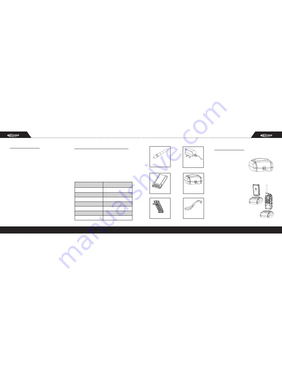
1. Unpacking and Checking

Antenna    

Battery    

Belt Clip   

Charger    

Power Adapter   

Hand Strap   

Instruction Manual   

Antenna

Power
Adapter

Belt Clip

Charger

Hand Strap


Battery

2. Preparation

Unpack  the  radio  carefully.  We  recommend  that 

you  check  the  radio  and  the  supplied  accessories 

listed  in  the  following  table  before  discarding  the 

packing material. If any damage or loss has occurred 

during  shipment,  please  contact  the  dealer  without 

delay. 

Supplied Accessories

Item

Quantity

2.1 Charging the Battery

Plug  the  adapter  into  an 

applicable  AC  outlet  and 

connect  the  power  adapter 

to  the  battery  charger.  The 

green LED will light up.

Place the battery or radio 

into  the  charger  slot,  and 

make  sure  the  radio  has 

been turned off.

Make  sure  the  battery  is 

well  connected  with  the 

charger. Then the red LED will 

light  up,  and  the  green  LED 

will  be  out,  which  indicates 

that the charging starts. 

Summary of Contents for PT578

Page 1: ...PT578 FM HANDHELD TRANSCEIVER INSTRUCTION MANUAL ...

Page 2: ...two way radios produced by Shenzhen Kirisun Electronics Co Ltd We believe two way radio which always incorporates the latest technology can bring great convenience to your life and work We also believe that the quality and function of two way radio can meet your demands for reliable communication ...

Page 3: ...ion Precautions in Use Please comply with the following attentions to avoid fire bodily injury and damage to the radio The radio is recommended to transmit for 1 minute and receive for 4 minutes Long time transmitting or con tinuous working in high power mode will make the rear side of the radio generate heat Please do not disassemble or assemble the radio un der any circumstances Please do not ex...

Page 4: ...ter Belt Clip Charger Hand Strap Battery 2 Preparation Unpack the radio carefully We recommend that you check the radio and the supplied accessories listed in the following table before discarding the packing material If any damage or loss has occurred during shipment please contact the dealer without delay Supplied Accessories Item Quantity 2 1 Charging the Battery Plug the adapter into an applic...

Page 5: ...ths or the radio is not in the low battery alarm state otherwise it will have bad effects on the battery s service life and performance Remove the battery from the charger after charging When the radio is in the low battery alarm state please recharge the battery before use Do not turn the radio power on by force otherwise it will have bad effects on its service life and performance Do not recharg...

Page 6: ...e radio is in low power B On Off Volume Control Knob Turn clockwise until you hear a click to turn the radio power on Turn counterclockwise until you hear a click to turn it off Rotate it to adjust the volume after turning on the radio C Channel Selector Knob Rotate to select channel 1 16 D Antenna E Top Button programmable button F PTT Push To Talk Button Press and hold the PTT button and speak i...

Page 7: ...ble Buttons The dealer can assign one of the following auxiliary functions to the top button side button 1 or side button 2 Description Description No function is assigned Press the preprogrammed Lone Worker button to start stop lone working Press the preprogrammed Emergency Alarm button to make an alarm tone according to the setting of the pro gramming software or send your ID or background sound...

Page 8: ...can prevent the user from continuously talking overlong and occupying one certain channel for an extended period of time and prevent the radio from heating due to continuous transmitting b The radio is set with a continuous transmitting limit If the radio is continuously transmitting longer than the time preset by the dealer the radio will make alarm and stop transmitting 2 TOT Rekey Time a A peri...

Page 9: ...the button set as Scan to start scanning While in scanning the radio checks every channel in the scan list and stops on which a signal is detected until that signal disappears If interval between signal disappearing and continuing scanning has been preset the radio will remain on that channel b Priority Scan One channel in the scan list can be set as the priority channel which enables it to have t...

Page 10: ...er Mode press the prepro grammed Lone Worker Reset button if a button is designated as the lone worker timer reset button or any button if any button is designated as the lone worker timer reset button to restart the lone worker timer 6 9 Emergency Alarm Press the preprogrammed Emergency Alarm button the pressing time should be longer than the debounce time of the emergency alarm switch to enter t...

Page 11: ...tion range A The antenna is in poor contact Please fasten the antenna head B The HF amplifier is broken please change it C The squelch level is so high that the squelch cannot be opened Please reset the squelch level D The mixer tube is broken please change it E The FM processing IC is broken please change it A The power module is broken so there is no power output Please change it B The microphon...

Page 12: ...tromagnetic Fields 3 kHz to 300 Ghz American National Standards Institute C95 3 1992 IEEE Recommended Practice for the Measurement of Potentially Hazardous Electromagnetic Fields RF and Microwave The forementioned accessories are authorized for use with this product Use of accessories other than those listed in the instruction specified may result in RF exposure levels exceeding the FCC requiremen...

Page 13: ...ONS OPERATING NOTES When transmitting with a portable radio hold the radio in a vertical position with its microphone 5 to 10 cm 2 to 4 inches away from your mouth Keep the antenna at least 2 5 cm 1 inch from your head and body If you wear a portable two way radio on your body ensure that the antenna is at least 2 5 centimeters 1 inch from your body when transmitting PRECAUTIONS WARNING NEVER hold...

Page 14: ...andheld Transceiver Model No PT578 This compliances is based on conformity with the following harmonised standards or documents 3 6Flrs ROBETA Building No 1 QiMin Road Song Ping Shan Area Science Industry Park Nanshan District Shenzhen 518057 P R China DECLARATION OF CONFORMITY WenLiang Fu General Manager Signature Kirisun Electronics Co Ltd Shenzhen 10 Dec 2008 Place and date of issue 1 ETSI EN30...

Reviews: