Chapter 6 Radio Debugging
Before test/debugging, make sure all the equipments have
been well connected to the ground!
Before test/debugging, make sure the antenna output terminal
has been connected properly to the corresponding devices and
load!
The transmitter output must pass RF power attenuator before
being connected to the standard signal source/ frequency
deviator/frequency spectrum!
When testing the receiver, make sure not to conduct
transmitting operation!
When in debugging/testing/service, make sure static free
measures for human body and equipments.
6.1 Service Equipment and Software.
The following equipments and software in Table 6.1 are
necessary for the service and test of the radio.
Table 6.1 For Test and Service: Equipment and Software
No.
1
2
3
4
5
6
7
8
9
10
11
12
13
14
15
Name
Computer
Programming
software
Programming
Cable
Tunning cable
Cloning line
DC regulated
power
Power
meter
Frequency meter
Frequency
Deviator
Digital Multimeter
Audio Signal
Generator
RF Power
attenuator
Standard signal
source
Oscillograph
Audio voltmeter
Parameter requirements
Above P2, compatible with IBM
PC, WINDOWS 98/ME/2000/XP
KSP7200
Output voltage: 7.5V, output current: 5A
Measuring rang: 0.5---10W
Frequency range: 100MHz500MHz
Impedance: 50Ù
Frequency range: 0.1600MHz
-6
Frequency precision: higher than
1
10
Sensitivity: higher than 100mV
Frequency range: DC600MHz
Measuring range: 0--
5kHz
Input impedance: higher than 10MÙ/V DC, with
the ability of testing voltage, current, impedance
Frequency range: 2---3000Hz
output level: 1---500mV
Attenuation: 40dB or 50dB
Supporting power: Higher than 10W
Frequency range: 10MHz---1000MHz
Output level: 0.1uV~32mV (-127dBm~-17dBm)
Frequency range: DC~20MHz
Test range: 10mV~20V
Test range: 10mV~10V
PT7200 SERVICE MANUAL
1
2
3
4
5
6
7
8
9
10
11
12
13
14
15
16
17
18
19
20
21
22
23
24
25
26
27
28
29
30
31
32
33
34
35
36
37
38
39
40
41
42
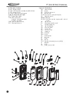
10
KEY PTT
SCREW 2*4
RUBBER KEY PTT
METAL DOME
PCB FOR PTT
FRONT CABINET
SPEAKER
DUST-PROOF NET FOR SPEAKER
WATERPROOF FOR ANTENNA SOCKET
WATERPROOF FOR ENCODER & VR
EMERGENCY RUBBER KEY
ANTENNA SOCKET
LIGHT GUIDER
NUT FOR ANTENNA SOCKET
ENCODER KNOB
VR KNOB
ENCODER CIRCLIP
VR CIRCLIP
ENCODER NUT
VR NUT
EARPHONE ADHESIVE TAPE
EARPHONE PCB
EARPHONE LABEL
EARPHONE COVER
SPECIAL SCREW M3.0*4 ANSI 4-40#
MIC WATERPROOF
DUST-PROOF NET FOR MIC
MIAN PCB
POGO PIN
MAIN WATERPROOF
POGO PIN SOCKET
AL CABINET
AL CABINET SPONGE
SCREW M2.0*8
POGO PIN WATERPROOF
RUBBERY STUFFER
COPING
CROSSBAR SPRING
SCREW M2.5*5
ANTENNA
SLIDE CROSSBAR
SCREW PLATE
201-007200-R04
301-20040G-R01
202-007200-R04
203-007200-R04
101-007200-R03
201-007200-R01
121-100000-R18
204-000558-R01
202-007200-R03
202-007200-R02
202-007200-R05
203-007200-R01
201-007200-R10
203-007200-R07
201-007200-R03
201-007200-R02
203-006800-R26
203-003208-R09
203-007200-R08
203-000558-R02
204-007200-R02
101-072001-R03
204-007200-R01
201-007200-R08
304-30040G-R01
202-000558-R09
204-006800-R06
203-007200-R02
202-007200-R01
201-007200-R09
203-007200-R03
204-007200-R03
301-20080G-R03
202-007200-R06
202-007200-R07
201-007200-R06
203-007200-R06
301-25050J-R01
201-007200-R07
204-007200-R05
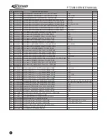
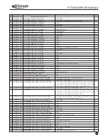
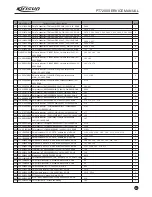
NO PART NUMBER DESCRIPTION NUMBER
1
12
1
1
1
1
1
1
1
1
1
1
1
1
1
1
1
1
1
1
1
1
1
1
1
1
1
1
3
1
1
1
1
2
1
2
1
1
2
1
1
2
Order
Summary of Contents for PT7200-01
Page 1: ...PROFESSIONAL TWO WAY RADIO PT7200 V071215 FM PORTABLE RADIO SERVICE MANUAL ...
Page 29: ...Figure 1 PT7200 Top Board Position Mark Diagram 136 174 ...
Page 30: ......
Page 31: ...Figure 1 PT7200 Top Board Position Mark Diagram 400 470 ...
Page 32: ......
Page 35: ...Figure 7 Schematic Circuit Pane Diagram PT7200 SERVICE MANUAL 26 33 ...


