background image


5. 

Disassembly 

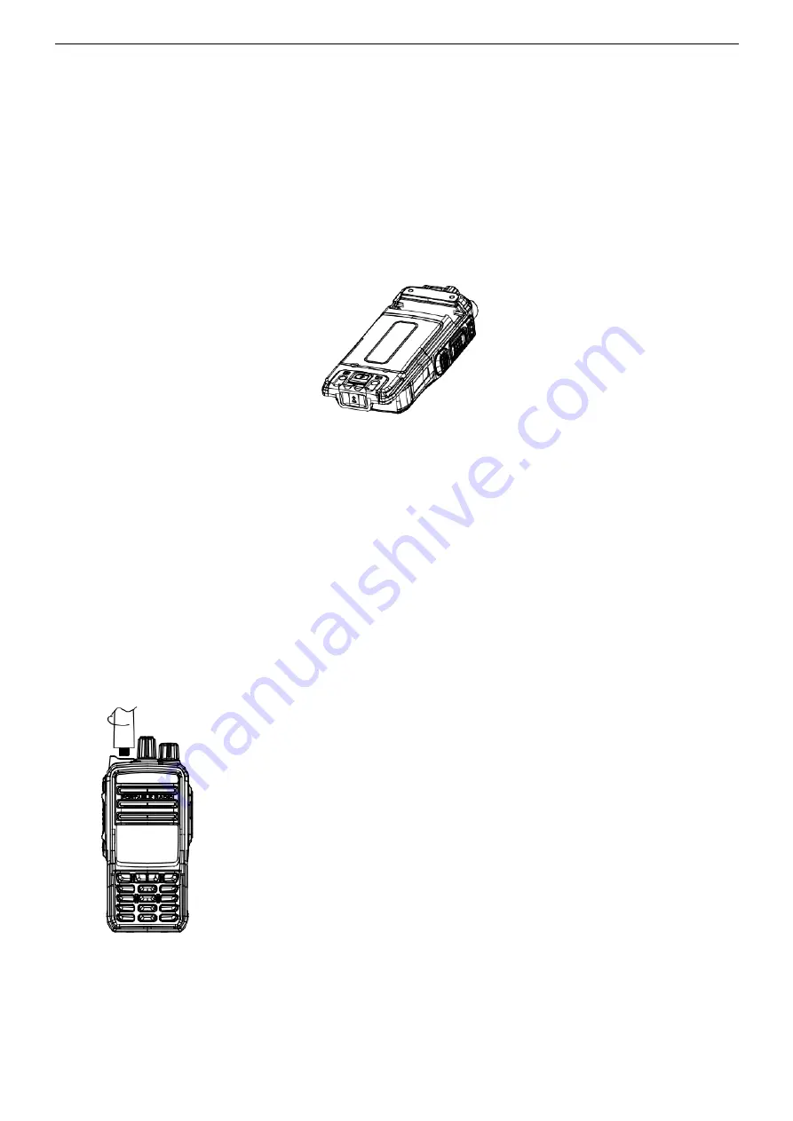
5.1 Installing/Uninstalling the Battery 

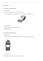
Installing the Battery 

1. Put the battery into the aluminum-alloy holder at the back of the radio. 

2. Push the battery upwards to the upper edge of the holder, and then push it down until a click is heard. 


Uninstalling the Battery 

1. Push upward the battery latch at the bottom of the radio. 

2. Take down the battery. 


5.2 Installing/Uninstalling the Antenna 

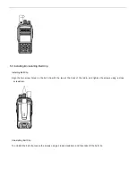
Installing the Antenna 

Insert the whorled end into the slot at the top of the radio, and then turn the antenna clockwise to tighten it. 


Uninstalling the Antenna 

Hold the lower part of the antenna, and then turn it counterclockwise. 

Summary of Contents for T60

Page 1: ...T60 T65 PoC Two way Radio Service Manual Version 1 0 Date2018 10 KIRISUN COMMUNICATION CO LTD Copyright 2018 Kirisun Communication Co Ltd All rights reserved ...

Page 2: ... Key Circuit 8 3 4 6 LCM Circuit 9 4 FUNCTIONS AND PARAMETERS 9 4 1 BASIC FUNCTIONS 9 4 2 ADVANCED FUNCTIONS 10 4 3 PARAMETER SETTINGS 10 5 DISASSEMBLY 11 5 1 INSTALLING UNINSTALLING THE BATTERY 11 5 2 INSTALLING UNINSTALLING THE ANTENNA 11 5 3 INSTALLING UNINSTALLING BELT CLIP 12 5 4 DISASSEMBLING ALUMINUM ALLOY HOLDER AND COMPONENTS OF MAIN PART 13 5 5 DETACHING MAIN BOARD FROM ALUMINUM ALLOY HO...

Page 3: ...arly required for example a hospitals health center or airport Explosive Harmful Gas It is better to shut down the radio in an area with explosive harmful gas for example the lower deck of a hull a facility for containing or transporting fuel oil or chemicals and an area with chemical substances or particles dust or metallic dusts in the air Shut down the radio if you are near a blast are or an el...

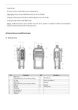
Page 4: ...ce will be provided and parts will be provided to maintenance stations and maintenance personnel at preferential prices after the warranty period 2 External View and LED Indicator 2 1 External View SN Part Name SN Part Name 1 Side Key 2 Programmable key no function by default 10 Microphone 2 PTT Key 11 Earphone USB port 3 Side Key 1 Programmable key no function by default 12 Belt clip 4 Antenna 13...

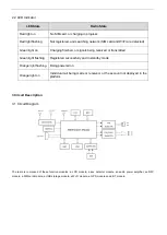
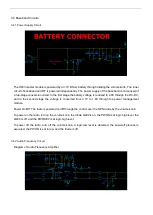
Page 5: ...d Green light flashing Registered successfully and in standby mode Orange light flashing Being powered on Orange light on Individual call being made or received or the account not deployed in the platform 3 Circuit Description 3 1 Circuit Diagram The radio is composed of these function modules a LCD module a key detector module an audio power amplifier an NFC module a SIM card module a USB storage...

Page 6: ...tegrated into the H603 module Signals are received and transmitted to RF module through the antenna 3 3 Wi Fi GPS Circuit Automatic switch between Wi Fi and GPS functions is achieved by the antenna switch The operation is performed by the H603 module ...

Page 7: ...e second stage the voltage is converted from 3 7V to 1 8V through the power management module Power On Off The radio is powered on off through the control over the NPN triode by the volume knob To power on the radio turn on the volume knob the triode Q402 is on the PWON is at logic high level the Q400 is off and the PWRKEY is at logic high level To power off the radio turn off the volume knob a lo...

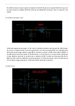
Page 8: ...ard clock signal SCLK the card reset signal SRST the card data signal SIO and the power supply detection signal PMU The frequency band of a SIM card is about 3 25MHz so the SIM socket is near the interface of the SIM module to avoid influence on communication signals due to wave distortion caused by an overlong wire A capacitor of 33PF is added onto the signal lines SCLK SRST and SIO to filter the...

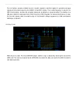
Page 9: ...ier The interface is a difference interface composed of AU_VIN0_N and AU_VIN0_P signals for reduced interference of noise For the both signals static is avoided using a TVS transient voltage suppressor or ESD electrostatic discharge component 3 4 5 Key Circuit Matrix keys are used The chip AW9523B judges whether a key is pressed by scanning the level at the GPIO port The level is processed by the ...

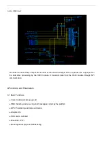
Page 10: ...by the H603 module It transmits data from the H603 module through SPI communication 4 Functions and Parameters 4 1 Basic Functions Voice Individual call group call SMS Sending and receiving short messages coded by the platform GPS Positioning and data submission Graphic UIs SOS alarm call alert Bluetooth Wi Fi Multi lingual display and broadcasting ...

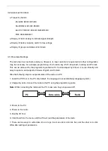
Page 11: ...gramming software PC Tool developed by Kirisun It is user friendly and easy to operate and supports Chinese English and Turkish Take the following steps to set parameters of the radio on a PC 1 Install the PC Tool on the PC By default the language is set automatically language system 2 Charge the radio Connect the radio to the PC using the programming cable Note While connecting the radio and the ...

Page 12: ...then push it down until a click is heard Uninstalling the Battery 1 Push upward the battery latch at the bottom of the radio 2 Take down the battery 5 2 Installing Uninstalling the Antenna Installing the Antenna Insert the whorled end into the slot at the top of the radio and then turn the antenna clockwise to tighten it Uninstalling the Antenna Hold the lower part of the antenna and then turn it ...

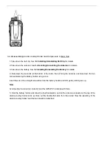
Page 13: ...ip Align the two screw holes on the belt clip with the two at the back of the radio and tighten the screws using a cross screwdriver Uninstalling Belt Clip To uninstall the belt clip loosen the screws using a cross screwdriver and then take off the belt clip ...

Page 14: ...f the radio the nut fixing the antenna and take down the two screws fastening the battery holder using a tool Insert the end of the straight screwdriver into the battery buckle and lift it gently until it goes up Note Avoid pulling the antenna conductor and the GPS Wi Fi antenna with force 5 Hold the battery holder and draw the shell backwards so that the antenna connector at the top of the alumin...

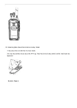
Page 15: ...g Main Board from Aluminum Alloy Holder 1 Take down the ten bolts from the main board 2 Screw down all the screws two at the PTT key Now the aluminum alloy holder and the main board are separated Explosion Diagram ...

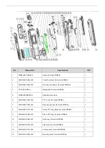
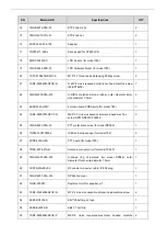
Page 16: ...48280 W0A Speaker dust screen 1 6 7MHP 4207 04A W0 PTT cover for model DP586 1 7 7MHP 4207 05A W0 Side key cap up for model DP586 1 8 7MHP 4207 01A W6 Plastic PTT key Blue for model DP586 1 9 7MHR 4207 03B W0 Silicon PTT key for model DP586 1 10 7MHR 4207 04A W3 Alarm key for model DP586 1 11 7MHR 4207 05A WC Light pipe for model DP586 1 12 7MHP 4182 01A W0 Volume knob for model DP990 1 13 7MHP 41...

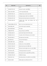
Page 17: ...1 24 7SMF 020037M SZCT N M2 0 3 7 cross recessed countersunk head machine screw AP570 DP570 T3500S 2 25 7MHS 4207 03A W PTT metal dome array for model DP586 1 26 7GCM 120070030 J IPEX anti drop sponge for model T65 3 27 6PD7 4232 HPA PTT board for model T60 1 28 7NRC 4078 01A N Antenna connector nut for model TP660 1 29 7MHR 4207 06A W0 O shape ring of antenna for model DP586 outer diameter 11mm w...

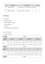
Page 18: ... 7GCM 020015010 Sponge mat for model DP990 2 47 7MHB 4323 02A W Insulative PET sheet for T60 GPS antenna 1 48 7MHB 4323 01A W Conductive cloth of GPS antenna for model T60 1 49 8ATX 1R575G WO GPS antenna for model T60 1 50 8ATX 2R4G WE Wi Fi Bluetooth antenna 1 51 7MJS 4038 01A W0 S760 spindle 1 52 7MHP 4253 03A W0 Earphone cover for model DP485 1 53 7MHR 1727 09A W3 Hand microphone case for R558 ...

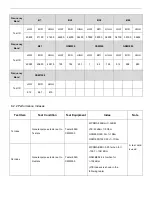
Page 19: ...t card General purpose tester CWM500 8960 6 2 Index Verification 6 2 1 Frequency Bands Model T60 T65 Frequency Band B1 2100MHz B2 1900MHz B5 850MHz B8 900MHz Test ID LOW MID HIGH LOW MID HIGH LOW MID HIGH LOW MID HIGH 10562 10700 10838 9662 9794 9938 4357 4408 4458 2937 3013 3088 Model T60 T65 Frequency Band B1 B3 B5 B8 Test ID LOW MID HIGH LOW MID HIGH LOW MID HIGH LOW MID HIGH 18050 18300 18550 ...

Page 20: ...62 124 512 698 885 Frequency Band GSM1900 Test ID LOW MID HIGH 512 661 810 6 2 2 Performance Indexes Test Item Test Condition Test Equipment Index Note Tx Index General purpose tester set to Tx state Tester 8960 CMW500 WCDMA 22dBm 1 3dBM LTE 22dBm 1 3Dbm GSM850 900 32 1 1Dbm GSM1800 1900 29 1 1Dbm A test card is used Rx Index General purpose tester set to Rx state Tester 8960 CMW500 WCDMA BER 0 00...

Page 21: ...cal Specifications General Specifications Frequency Range B1 B2 B5 B8 Group Capacity 16 Group Interval 5MHz Not exceed 5MHz Weight 300g include battery and antenna exclude belt clip Rated Operating Voltage 3 7V ...

Page 22: ... and widely applied to the production and testing in the communication industry It is used to test the performance of a mobile phone for example display and BER Power supply or battery of the main part Battery or power supply with an output of 3 7V DC 9 Troubleshooting SN Failure Description Troubleshooting 1 Red light flashing cannot login A Check the validity of the SIM card B Check whether the ...

Page 23: ...device is connected 3 Abnormal frequency programming A Check the wiring B Check whether a USB driver is installed C Check the contact of the earphone interface board In case of poor contact replace the USB socket ...

Page 24: ...Main Board Layout Diagrams ...

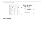
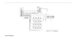
Page 25: ...Key Board Layout Diagrams Model T60 Only Key Board Diagram Model T60 Only ...

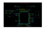
Page 26: ...Main Board Diagrams ...

Page 27: ......

Page 28: ......

Page 29: ......

Page 30: ......

Page 31: ......

Page 32: ......

Page 33: ......

Reviews: