TR850 Service Manual
96
L2011
0R
L2001
BLM11A601S
R2017
NC
C2011
104
C2024
47pF
C3111
103
C2012
101
C2020 82pF
L2006
12nH
C2018
3pF
C2019
2pF
R2016
NC
C2035
NC
C3109
10uF/16V
C3053
103
C2022
62pF
R2010
0R
R2015
NC
C2010
101
R3053
NC
L2013
0R
C2008
101
220R
R2012
220R
R2011
R2006
NC
C2014
104
1
2
3
4
U5002
LFCN-400
L2012 0R
1
2
3
IC6006 NC
R2009
27R
C2025
62pF
C2031
12pF
R1039
10K
L2004
1uH
C2037
NC
C2030
6pF
C2023 121
C2036
NC
C2013
104
C3113
10uF/16V
8.2K
R2007
C3110
101
C2039
NC
L2010 18nH
C2034
NC
C2038
104
C3040
101
R2008
NC
C2009
104
C2017
101
C2032
6pF
L2009 18nH
C2026 82pF
C2033
NC
C2021 121
51R
R2018
C3112
10uF/16V
L2002
BLM11A601S
1
2
3
4
5
Q3005
XC6209F501PR
1 NA
2 RFIN
3 NA
4 NA
NA 5
NA 6
RFOUT 7
NA 8
0
GND
IC3003
SPF5122
Q2002
2SC3356
8R
LO1
RXVCOOUT
Summary of Contents for TR850
Page 1: ......
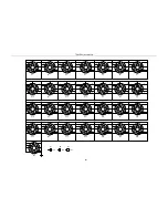
Page 45: ...TR850 Service Manual 5 4 Connection 1 2 3 4 6 8 7 5 9 10 13 14 15 16 18 17 11 12 41 ...
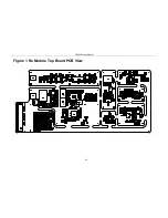
Page 90: ...TR850 Service Manual Figure 1 Rx Module Top Board PCB View 86 ...
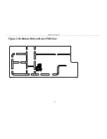
Page 91: ...TR850 Service Manual Figure 2 Rx Module Bottom Board PCB View 87 ...
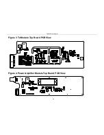
Page 93: ...TR850 Service Manual Figure 5 Power Amplifier Module Bottom Board PCB View 89 ...
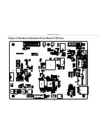
Page 94: ...TR850 Service Manual Figure 6 Baseband Mainboard Top Board PCB View 90 ...
Page 95: ...TR850 Service Manual Figure 7 Baseband Mainboard Bottom Board PCB View 91 ...
Page 97: ...TR850 Service Manual Figure 10 Power Board Top Board PCB View 93 ...
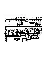
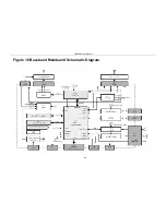
Page 114: ...TR850 Service Manual Figure 16 Baseband Mainbaord Schematic Diagram 110 ...
Page 169: ...TR850 Service Manual Figure 1 Rx module Top Board Position Mark Diagram 165 ...
Page 170: ...TR850 Service Manual Figure 2 Rx Module Buttom Board Position Mark Diagram 166 ...
Page 172: ...TR850 Service Manual Figure 5 Power Amplifier Module Buttom Position Mark Diagram 168 ...
Page 173: ...TR850 Service Manual Figure 6 Baseband Mainboard Top Board Position Mark Diagram 169 ...
Page 174: ...TR850 Service Manual Figure 7 Baseband Mainboard Buttom Board Position Mark Diagram 170 ...
Page 176: ...TR850 Service Manual Figure 10 Power Board Top Board Position Mark Diagram 172 ...
Page 193: ...TR850 Service Manual Figure 16 Baseband Mainboard Schematic Diagram 189 ...

