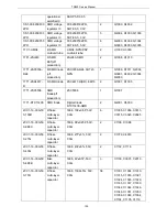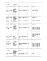
TR850 Service Manual
C3096, C3098, C3111,
C5000, C5001, C5002,
C5004, C5006, C5007,
C5008, C6004, C6013,
C1041, C1048, C4008,
C4000, C4001
2CC1-16-X7R50
0-152K
flake
multi-layer
capacitor
1608, 1500P±10%, 50V,
X7R
1
C3085
2CC1-16-X7R50
0-182K
R flake
multi-layer
capacitor
1608, 1800P±10%, 50V,
X7R
1
C3077
2CC1-16-X7R50
0-271K
R flake
multi-layer
capacitor
1608, 270P±10%, 50V,
X7R
2
C1087, C1088
2CC1-16-X7R50
0-331K
flake
multi-layer
capacitor
1608, 330P±10%, 50V,
X7R
5
C3114, C3054, C3068,
C3108, C3115
2CC1-16-Y5V16
0-104Z
flake
multi-layer
capacitor
1608, 100nF+80%/-20%,
16V, Y5V
24
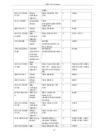
C1065, C1078, C1081,
C1083, C1106, C1113,
C2009, C2011, C2013,
C2014, C2038, C3041,
C3045, C3049, C3071,
C3079, C3081, C3086,
C3087, C3089, C3090,
C3092, C3101, C3103
2CC1-16-Y5V25
0-105Z
flake
multi-layer
capacitor
1608,
1μF+80%/-20%,
25V, Y5V
3
R6004, C6014, C6015
2CE1-VS250-10
1M0607D
SMD
aluminum
electrolytic
capacitor
SMD-6.3x7.7mm,
100uF/25V
1
C5003
2CT1-TS32-100-
220M
SMD tantalum
capacitor
3216,
22μF±20%, 10V,
TS series(A level)
1
C5005
2CT1-TS32-100-
2R2M
R SMD
tantalum
capacitor
3216,
2.2μF±20%, 10V,
TS series(A level)
1
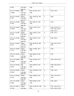
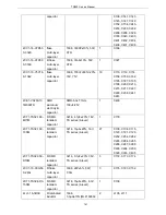
C1075
2CT1-TS32-160-
100M
R SMD
tantalum
capacitor
3216,
10μF±20%, 16V,
TS series(A level)
29
C4029, C4024, C4040,
C4045, C4047, C4052,
C6007, C1000, C1005,
C1014, C1019, C1020,
C1025, C1030, C1031,
C6002, C6008, C6011,
C3029, C3030, C3046,
C3067, C3094, C3097,
132
Summary of Contents for TR850
Page 1: ......
Page 45: ...TR850 Service Manual 5 4 Connection 1 2 3 4 6 8 7 5 9 10 13 14 15 16 18 17 11 12 41 ...
Page 90: ...TR850 Service Manual Figure 1 Rx Module Top Board PCB View 86 ...
Page 91: ...TR850 Service Manual Figure 2 Rx Module Bottom Board PCB View 87 ...
Page 93: ...TR850 Service Manual Figure 5 Power Amplifier Module Bottom Board PCB View 89 ...
Page 94: ...TR850 Service Manual Figure 6 Baseband Mainboard Top Board PCB View 90 ...
Page 95: ...TR850 Service Manual Figure 7 Baseband Mainboard Bottom Board PCB View 91 ...
Page 97: ...TR850 Service Manual Figure 10 Power Board Top Board PCB View 93 ...
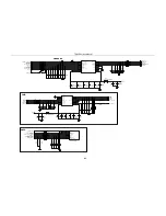
Page 114: ...TR850 Service Manual Figure 16 Baseband Mainbaord Schematic Diagram 110 ...
Page 169: ...TR850 Service Manual Figure 1 Rx module Top Board Position Mark Diagram 165 ...
Page 170: ...TR850 Service Manual Figure 2 Rx Module Buttom Board Position Mark Diagram 166 ...
Page 172: ...TR850 Service Manual Figure 5 Power Amplifier Module Buttom Position Mark Diagram 168 ...
Page 173: ...TR850 Service Manual Figure 6 Baseband Mainboard Top Board Position Mark Diagram 169 ...
Page 174: ...TR850 Service Manual Figure 7 Baseband Mainboard Buttom Board Position Mark Diagram 170 ...
Page 176: ...TR850 Service Manual Figure 10 Power Board Top Board Position Mark Diagram 172 ...
Page 193: ...TR850 Service Manual Figure 16 Baseband Mainboard Schematic Diagram 189 ...


