TR850 Service Manual
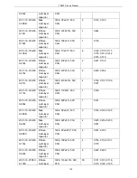
inductor, muRata brand
2LW1-20UC-331
J
SMD wire
winding
inductor
2012, 330nH±5%,
ceramic core (high
frequency)
3
L1019, L1020, L4001
2LW1-25UC-103
J
R SMD wire
winding
inductor
2520,
10μH±5%,
ceramic core
(FLM2520-100J)
4
L1022, L3005, L4002,
L4003
2RE1-16-1000
SMD
precision
resistor
1608,
100Ω±1%
8
R1008, R1009, R1010,
R1013, R1014, R1016,
R1022, R1024
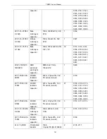
2RE1-16-1200
SMD
precision
resistor
1608,
120Ω±1%
7
R1005, R1021, R1025,
C4009, C4010, R3002,
R3003
2RE1-16-3301
SMD
precision
resistor
1608, 3.3K±1%
2
R3029, C3083
2RE1-16-47R0
SMD
precision
resistor
1608,
47Ω±1%
2
R1019, R3000
2RS1-16-000O
R flake
resistor
1608,
0Ω
19
R1017, R1018, R1029,
R2010, L2012, C3039,
L3015, R3018, R3027,
R3028, R3031, R3038,
R3042, R6012, R6013,
R1020, R6040, R6041,
R4003
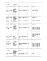
2RS1-16-102J
R flake
resistor
1608, 1K±5%
6
R1023, R1028, R1042,
R3036, R4004, R4009
2RS1-16-103J
R flake
resistor
1608, 10K±5%
19
R1035, R1036, R1037,
R1007, R1011, R1030,
R1031, R1032, R1033,
R1034, R1039, R1040,
R3017, R6007, R6009,
R1041, R4002, R4007,
R4008
2RS1-16-104J
R flake
resistor
1608, 100K±5%
13
R3005, R3006, R3007,
R3008, R3009, R3010,
R3011, R3012, R3013,
R3014, R3015, R3016,
R4006
2RS1-16-124J
R flake
resistor
1608, 120K±5%
1
R1026
2RS1-16-153J
R flake
resistor
1608, 15K±5%
1
R6005
2RS1-16-182J
R flake
resistor
1608, 1.8K±5%
2
R3024, R3026
134
Summary of Contents for TR850
Page 1: ......
Page 45: ...TR850 Service Manual 5 4 Connection 1 2 3 4 6 8 7 5 9 10 13 14 15 16 18 17 11 12 41 ...
Page 90: ...TR850 Service Manual Figure 1 Rx Module Top Board PCB View 86 ...
Page 91: ...TR850 Service Manual Figure 2 Rx Module Bottom Board PCB View 87 ...
Page 93: ...TR850 Service Manual Figure 5 Power Amplifier Module Bottom Board PCB View 89 ...
Page 94: ...TR850 Service Manual Figure 6 Baseband Mainboard Top Board PCB View 90 ...
Page 95: ...TR850 Service Manual Figure 7 Baseband Mainboard Bottom Board PCB View 91 ...
Page 97: ...TR850 Service Manual Figure 10 Power Board Top Board PCB View 93 ...
Page 114: ...TR850 Service Manual Figure 16 Baseband Mainbaord Schematic Diagram 110 ...
Page 169: ...TR850 Service Manual Figure 1 Rx module Top Board Position Mark Diagram 165 ...
Page 170: ...TR850 Service Manual Figure 2 Rx Module Buttom Board Position Mark Diagram 166 ...
Page 172: ...TR850 Service Manual Figure 5 Power Amplifier Module Buttom Position Mark Diagram 168 ...
Page 173: ...TR850 Service Manual Figure 6 Baseband Mainboard Top Board Position Mark Diagram 169 ...
Page 174: ...TR850 Service Manual Figure 7 Baseband Mainboard Buttom Board Position Mark Diagram 170 ...
Page 176: ...TR850 Service Manual Figure 10 Power Board Top Board Position Mark Diagram 172 ...
Page 193: ...TR850 Service Manual Figure 16 Baseband Mainboard Schematic Diagram 189 ...


