TR850 Service Manual
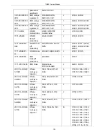
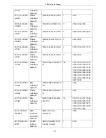
R56K)
2CC1-16-C0G50
0-151J
R flake
multi-layer
capacitor
1608, 150P±5%, 50V,
C0G
1
C3058
2LL1-16-R22K
R laminated
inductor
1608,
0.22μH±10%(MLF1608D
R22K TA00)
1
L3017
2RS1-16-271J
R flake
resistor
1608,
270Ω±5%
1
L3018
2CC1-16-C0G50
0-3R0B
flake
multi-layer
capacitor
1608, 3P±0.1P, 50V,
C0G
2
C1101, C1116
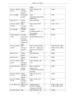
1IS1-AD9864
IF digital
system
AD9864,
LFCSP-N48_B7X6_75_
P0_5, pb-free
1
U4000
1IM1-AT24C08C
N-SH
E R SMD
memorizor IC
for analog
commercial
portable and
radio
EEPROPM,
AT24C08CN-SH(8-SOIC
)
1
IC6005
2CC1-16-Y5V50
0-104Z
flake
multi-layer
capacitor
1608,
0.1μF+80%/-20%,
50V, Y5V, replacement
part:2CC1-16-Y5V250-1
04Z
7
C4004, C4018, C4023,
C4030, C4031, C4046,
C4055
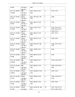
2RS1-16-561J
R flake
resistor
1608,
560Ω±5%
1
R4005
2RS1-16-203J
R flake
resistor
1608, 20K±5%
1
R4001
2CC1-16-C0G50
0-181J
flake
multi-layer
capacitor
1608, 180P±5%, 50V,
C0G
1
C4020
2LW1-25UC-332
K
SMD wire
winding
inductor
2520,
3.3μH±10%,
ceramic core
(NL252018T-3R3K/NLV2
5T-3R3K)
1
L4005
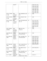
2CC1-16-C0G50
0-130J
R flake
multi-layer
capacitor
1608, 13P±5%, 50V,
C0G
1
C3018
2CC1-16-C0G50
0-110J
R flake
multi-layer
capacitor
1608, 11P±5%, 50V,
C0G
1
C3026
2LH1-0908-140G SMD air core
inductor
0908SQ-14NJLC,
14nH±2%, 0908SQ
package, COILCRAFT
6
L3025, L3026, L3027,
L3028, L3029, L3030
2CC1-16-C0G50
flake
1608, 680P±5%, 50V,
1
C3008
137
Summary of Contents for TR850
Page 1: ......
Page 45: ...TR850 Service Manual 5 4 Connection 1 2 3 4 6 8 7 5 9 10 13 14 15 16 18 17 11 12 41 ...
Page 90: ...TR850 Service Manual Figure 1 Rx Module Top Board PCB View 86 ...
Page 91: ...TR850 Service Manual Figure 2 Rx Module Bottom Board PCB View 87 ...
Page 93: ...TR850 Service Manual Figure 5 Power Amplifier Module Bottom Board PCB View 89 ...
Page 94: ...TR850 Service Manual Figure 6 Baseband Mainboard Top Board PCB View 90 ...
Page 95: ...TR850 Service Manual Figure 7 Baseband Mainboard Bottom Board PCB View 91 ...
Page 97: ...TR850 Service Manual Figure 10 Power Board Top Board PCB View 93 ...
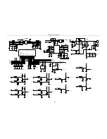
Page 114: ...TR850 Service Manual Figure 16 Baseband Mainbaord Schematic Diagram 110 ...
Page 169: ...TR850 Service Manual Figure 1 Rx module Top Board Position Mark Diagram 165 ...
Page 170: ...TR850 Service Manual Figure 2 Rx Module Buttom Board Position Mark Diagram 166 ...
Page 172: ...TR850 Service Manual Figure 5 Power Amplifier Module Buttom Position Mark Diagram 168 ...
Page 173: ...TR850 Service Manual Figure 6 Baseband Mainboard Top Board Position Mark Diagram 169 ...
Page 174: ...TR850 Service Manual Figure 7 Baseband Mainboard Buttom Board Position Mark Diagram 170 ...
Page 176: ...TR850 Service Manual Figure 10 Power Board Top Board Position Mark Diagram 172 ...
Page 193: ...TR850 Service Manual Figure 16 Baseband Mainboard Schematic Diagram 189 ...

