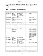
TR850 Service Manual
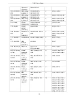
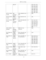
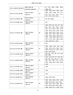
R3K TA00)
2LW1-16UC-181
J
SMD wire
winding
inductor
1608, 180nH±5%,
ceramic core
(C1608CB-R18J)
1
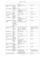
L205
2LW1-16UC-560
G
SMD wire
winding
inductor
1608, 56nH±2%,
ceramic core
(C1608CB-56NG)
1
L113
2LW1-16UC-R33
G
SMD wire
winding
inductor
1608,
330nH±2%(C1608BR33
G), pb-free
6
L103, L104, L111, L115,
L116, L120
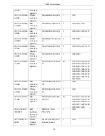
2LW1-20UC-102
J
SMD wire
winding
inductor
2012,
1μH±5%, ceramic
core (C2012C-1R0J)
2
L214, L106
2LW1-20UC-470
GB
SMD wire
winding
inductor
2012, 47nH±2%, 500mA,
LQW2BAS47NG00,
SMD wire winding
inductor, muRata brand
1
L119
2LW1-20UC-560
JA
R SMD wire
winding
inductor
2012, 56nH±5%,
ceramic core
(C2012C-56NJ)
2
L209, L210
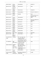
2LW1-20UC-221
J
R SMD wire
winding
inductor
2012, 220nH±5%,
ceramic core
(LQN21AR22J/LQW2BH
NR22J03L)
1
L118
2LW1-20UC-330
GC
SMD wire
winding
inductor
2012, 33nH±2%, 500mA,
LQW2BAS33NG00,
SMD wire winding
inductor, muRata brand
1
L107
2LW1-25UC-103
J
R SMD wire
winding
inductor
2520,
10μH±5%,
ceramic core
(FLM2520-100J)
1
L122
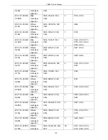
2RE1-16-1000
SMD
precision
resistor
1608,
100Ω±1%
11
R129, R124, R105,
R106, R113, R115,
R117, R119, R120,
R121, R128
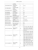
2RE1-16-1001
SMD
precision
resistor
1608, 1K±1%
2
R134, R135
2RE1-16-1200
SMD
precision
resistor
1608,
120Ω±1%
1
R108
2RE1-16-8201
R SMD
precision
resistor
1608, 8.2K±1%
2
R342, R403
2RS1-16-000O
R flake
resistor
1608,
0Ω
21
C191, R131, R137,
R335, R122, R123,
142
Summary of Contents for TR850
Page 1: ......
Page 45: ...TR850 Service Manual 5 4 Connection 1 2 3 4 6 8 7 5 9 10 13 14 15 16 18 17 11 12 41 ...
Page 90: ...TR850 Service Manual Figure 1 Rx Module Top Board PCB View 86 ...
Page 91: ...TR850 Service Manual Figure 2 Rx Module Bottom Board PCB View 87 ...
Page 93: ...TR850 Service Manual Figure 5 Power Amplifier Module Bottom Board PCB View 89 ...
Page 94: ...TR850 Service Manual Figure 6 Baseband Mainboard Top Board PCB View 90 ...
Page 95: ...TR850 Service Manual Figure 7 Baseband Mainboard Bottom Board PCB View 91 ...
Page 97: ...TR850 Service Manual Figure 10 Power Board Top Board PCB View 93 ...
Page 114: ...TR850 Service Manual Figure 16 Baseband Mainbaord Schematic Diagram 110 ...
Page 169: ...TR850 Service Manual Figure 1 Rx module Top Board Position Mark Diagram 165 ...
Page 170: ...TR850 Service Manual Figure 2 Rx Module Buttom Board Position Mark Diagram 166 ...
Page 172: ...TR850 Service Manual Figure 5 Power Amplifier Module Buttom Position Mark Diagram 168 ...
Page 173: ...TR850 Service Manual Figure 6 Baseband Mainboard Top Board Position Mark Diagram 169 ...
Page 174: ...TR850 Service Manual Figure 7 Baseband Mainboard Buttom Board Position Mark Diagram 170 ...
Page 176: ...TR850 Service Manual Figure 10 Power Board Top Board Position Mark Diagram 172 ...
Page 193: ...TR850 Service Manual Figure 16 Baseband Mainboard Schematic Diagram 189 ...

