TR850 Service Manual
Tx/Rx index testing.
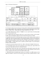
The output power of audio power amplifier (U31) is 1W, which is used for local monitoring or tested
speech output.
Network interface (U17) is the TRx components of 10/100M single Ethernet physical layer, and it is used
to the tuning of various parameter setting and communication control.
UART- Universal Asynchronous Receiver/Transmitter(U32)achieves the RS232 electrical level switch,
when it communicates with the PC, it can initiate the programming burning, programming tuning
information printing, and etc.
3.3.2. Power Section
Figure 3-8 Whole Unit Power
As Figure 3-8 shows, the whole unit power supply employs adaptive ac/dc power supply with AC priority
and DC/AC auto switch. The output DC voltage which is switched and protected by the electric relay will
be divided into two paths. One path is for the RF power amplification, and the other is for banseband
mainboard. The switch in the front panel turns the power on/off via the electric relay U2. The protection
circuit will cut off all the DC output when the DC exceeds 18V.
The AC/DC switching part employs an independent module power supply(320W), and it supports the AC
input range between 100V-240V, nominal output DC voltage is 12V, and the factory set is 13.2V.
The rated AC input voltage is between 100-240V, the socket is built in the dual protective tube.
Specification of the protective tube is 2.5A, 5x20mm ceramic tube, slow type.
The rated DC input voltage is 13.6V with the rated current being 15A. The protective tube is included in
the DC accessories.
Power Switch and AC/DC Switch
As the Figure 3-8 shows, the electric relay is switched on for the AC power supply and it will cut off the DC
point. The 13.2VDC output from the ACDC module is connected to U2 through the U1 contact. If the panel
switch (J5) is on, the electric relay (U2) will be switched on, so is the repeater.
11
Summary of Contents for TR850
Page 1: ......
Page 45: ...TR850 Service Manual 5 4 Connection 1 2 3 4 6 8 7 5 9 10 13 14 15 16 18 17 11 12 41 ...
Page 90: ...TR850 Service Manual Figure 1 Rx Module Top Board PCB View 86 ...
Page 91: ...TR850 Service Manual Figure 2 Rx Module Bottom Board PCB View 87 ...
Page 93: ...TR850 Service Manual Figure 5 Power Amplifier Module Bottom Board PCB View 89 ...
Page 94: ...TR850 Service Manual Figure 6 Baseband Mainboard Top Board PCB View 90 ...
Page 95: ...TR850 Service Manual Figure 7 Baseband Mainboard Bottom Board PCB View 91 ...
Page 97: ...TR850 Service Manual Figure 10 Power Board Top Board PCB View 93 ...
Page 114: ...TR850 Service Manual Figure 16 Baseband Mainbaord Schematic Diagram 110 ...
Page 169: ...TR850 Service Manual Figure 1 Rx module Top Board Position Mark Diagram 165 ...
Page 170: ...TR850 Service Manual Figure 2 Rx Module Buttom Board Position Mark Diagram 166 ...
Page 172: ...TR850 Service Manual Figure 5 Power Amplifier Module Buttom Position Mark Diagram 168 ...
Page 173: ...TR850 Service Manual Figure 6 Baseband Mainboard Top Board Position Mark Diagram 169 ...
Page 174: ...TR850 Service Manual Figure 7 Baseband Mainboard Buttom Board Position Mark Diagram 170 ...
Page 176: ...TR850 Service Manual Figure 10 Power Board Top Board Position Mark Diagram 172 ...
Page 193: ...TR850 Service Manual Figure 16 Baseband Mainboard Schematic Diagram 189 ...


