TR850 Service Manual
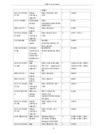
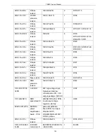
1S
suppression
filter
18AG601S(0138-05)
09,L110,L112,L114,L121
,L123,L202,L207,L300,R
301,L301,R302,R303,R3
04,R305,R306,R307,R3
08,R309,R310,R311,R3
12,R329,R351
5FE1-BLM21P30
0S
R SMD EMI
suppression
filter
2012,BLM21P300S/BLM
21PG300S(0149-05)
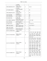
1
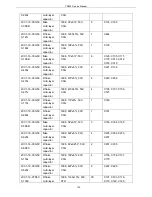
L400
5OT1-12R8-ACL
4-3225
SMD
temperature
compensated
crystal
oscillator
KDS,12.8MHz±1.5ppm,
Vc=1.5±1V
range:±35ppm,-40
℃~
85,3225
1
X100
6PD7-1861-HLC
Crystal
adaptor board
Thickness 0.6mm,FR4
material
1
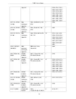
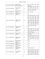
6PM7-4067-HTB
DR650-02 TX
board
DR650-DVC0-TXBORA
D-20130319.PCB,
thickness1.6MM,FR-4,70
X194M,4layers
1
2CC1-16-Y5V16
0-474Z
R flake
multi-layer
capacitor
1608,470nF+80%/-20%,
16V,Y5V
1
R344
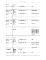
2RS1-16-183J
R flake
resistor
1608,18K±5%
1
C339
2CC1-16-C0G50
0-270J
R flake
multi-layer
capacitor
1608,27P±5%,50V,C0G
1
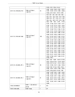
C137
2RS1-32-000O
R flake
resistor
3216,0Ω±5%
1
U402
2RS1-16-222J
R flake
resistor
1608,2.2K±5%
1
R138
2CC1-16-X7R50
0-202K
flake
multi-layer
capacitor
1608,2000P±10%,50V,X
7R
1
C198
2RS1-16-820J
flake resistor
1608,82Ω±5%
1
R126
2CC1-16-C0G50
0-300J
R flake
multi-layer
capacitor
1608,30P±5%,50V,C0G
2
C128,C168
2CC1-16-C0G50
0-9R0C
R flake
multi-layer
capacitor
1608,9P±0.25P,50V,C0G 1
C134
0SS2-4095-HTA
STR-V TX
board plug-in
unit
STR-V, pb-free
1
IC102,IC104,IC105,IC30
2
3CB3-A2548WV-
Plug-in
2*10 socket(male),
1
J300
150
Summary of Contents for TR850
Page 1: ......
Page 45: ...TR850 Service Manual 5 4 Connection 1 2 3 4 6 8 7 5 9 10 13 14 15 16 18 17 11 12 41 ...
Page 90: ...TR850 Service Manual Figure 1 Rx Module Top Board PCB View 86 ...
Page 91: ...TR850 Service Manual Figure 2 Rx Module Bottom Board PCB View 87 ...
Page 93: ...TR850 Service Manual Figure 5 Power Amplifier Module Bottom Board PCB View 89 ...
Page 94: ...TR850 Service Manual Figure 6 Baseband Mainboard Top Board PCB View 90 ...
Page 95: ...TR850 Service Manual Figure 7 Baseband Mainboard Bottom Board PCB View 91 ...
Page 97: ...TR850 Service Manual Figure 10 Power Board Top Board PCB View 93 ...
Page 114: ...TR850 Service Manual Figure 16 Baseband Mainbaord Schematic Diagram 110 ...
Page 169: ...TR850 Service Manual Figure 1 Rx module Top Board Position Mark Diagram 165 ...
Page 170: ...TR850 Service Manual Figure 2 Rx Module Buttom Board Position Mark Diagram 166 ...
Page 172: ...TR850 Service Manual Figure 5 Power Amplifier Module Buttom Position Mark Diagram 168 ...
Page 173: ...TR850 Service Manual Figure 6 Baseband Mainboard Top Board Position Mark Diagram 169 ...
Page 174: ...TR850 Service Manual Figure 7 Baseband Mainboard Buttom Board Position Mark Diagram 170 ...
Page 176: ...TR850 Service Manual Figure 10 Power Board Top Board Position Mark Diagram 172 ...
Page 193: ...TR850 Service Manual Figure 16 Baseband Mainboard Schematic Diagram 189 ...


