TR850 Service Manual
for analog
commercial
portable and
mobile
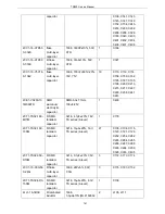
0SS2-4071-HPC
STR-U power
amplification
board plug-in
unit (130722)
STR-U power
amplification board
plug-in unit, pb-free
1
3CB1-DC002
STR-U power
amplification
board power
supply socket
DC-002, combination
key, plastic p
two copper tablets,
pb-free
1
J302
3CP3-LCP200
DM850 power
supply socket
LCP with plastic pedestal
with ,2Pin, nickel-plated
brass pin, pb-free
1
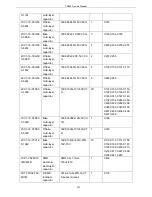
7MBC-4073-01A
-N
STM-U power
connecting
terminal
nickel-plated brass,
pb-free
2
2RV3-22ZR-10D
R plug-in unit
piezoresistor
22ZR-10D
1
R306
3CR7-SMA-50K
WE-2
RF coaxial
connector
SMA-50KWE-2, 5PIN
plug-in unit, 90 degrees,
length
23mm.pitch:2.54mm
1
J100
3CB3-A2548WV-
2X05P
Plug-in unit
board-to-boar
d connector
A2548WV-2X05P, male,
180 degrees, interval
2.54mm,20.32mmX9mm
X9.1mm,
1
J300
1IS3-DS18B20
Integrated IC
Plug-in unit temperature
sensor ,3.0V-5.5V power
supply,
-55
℃
--125
℃
,TO-92
1
IC101
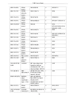
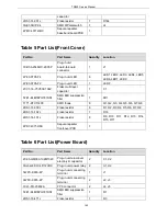
Table 4 Part List(Baseband Board)
Part No.
Part Name
Quantity
Location
3CB3-VH3096-2P
DC supply socket
1
J1
3CB3-S6160BK1
Plug-in unit
board-to-board
connector
2
J2
3CR7-SMA-50KE
RF coaxial connector
3
J6, J7, J8
3CB3-A2548WV-2X05P
Plug-in unit
board-to-board
4
J5, J18, J19, J23
155
Summary of Contents for TR850
Page 1: ......
Page 45: ...TR850 Service Manual 5 4 Connection 1 2 3 4 6 8 7 5 9 10 13 14 15 16 18 17 11 12 41 ...
Page 90: ...TR850 Service Manual Figure 1 Rx Module Top Board PCB View 86 ...
Page 91: ...TR850 Service Manual Figure 2 Rx Module Bottom Board PCB View 87 ...
Page 93: ...TR850 Service Manual Figure 5 Power Amplifier Module Bottom Board PCB View 89 ...
Page 94: ...TR850 Service Manual Figure 6 Baseband Mainboard Top Board PCB View 90 ...
Page 95: ...TR850 Service Manual Figure 7 Baseband Mainboard Bottom Board PCB View 91 ...
Page 97: ...TR850 Service Manual Figure 10 Power Board Top Board PCB View 93 ...
Page 114: ...TR850 Service Manual Figure 16 Baseband Mainbaord Schematic Diagram 110 ...
Page 169: ...TR850 Service Manual Figure 1 Rx module Top Board Position Mark Diagram 165 ...
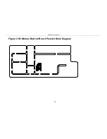
Page 170: ...TR850 Service Manual Figure 2 Rx Module Buttom Board Position Mark Diagram 166 ...
Page 172: ...TR850 Service Manual Figure 5 Power Amplifier Module Buttom Position Mark Diagram 168 ...
Page 173: ...TR850 Service Manual Figure 6 Baseband Mainboard Top Board Position Mark Diagram 169 ...
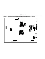
Page 174: ...TR850 Service Manual Figure 7 Baseband Mainboard Buttom Board Position Mark Diagram 170 ...
Page 176: ...TR850 Service Manual Figure 10 Power Board Top Board Position Mark Diagram 172 ...
Page 193: ...TR850 Service Manual Figure 16 Baseband Mainboard Schematic Diagram 189 ...

