TR850 Service Manual
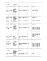
1DR1-SS36
SMD commutation
diode
1
D3
1DS1-DA2S10100L
SMD switch diode
4
D8, D11, D12, D13
1DS1-HVC131
SMD switch diode
2
D9, D15
1DP1-BV03C
TVS diode
1
D10
1DS1-DAN222
SMD switch diode
1
D14
1DR1-MMBZ20VALT1G
TVS diode
6
D16, D17, D18, D19, D20, D5
1TT1-2SA1641-S
SMD triode
1
Q42
1DS1-DA204U
SMD switch diode
2
D7, D21
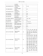
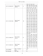
5FE1-BLM15AG221SN1D EMI suppression filter
50
FB1, FB2, FB3, FB4, FB5, FB17,
FB18, , FB25, FB26, FB27, FB28,
FB29, FB30, FB31, FB35, FB36,
FB37, FB38, FB39, FB40, FB41,
FB42, FB43, FB44, FB45, FB46,
FB47, FB48, FB49, FB50, FB51,
FB52, FB53, FB54, FB55, FB56,
FB57, FB58, FB59, FB60, FB62,
FB63, FB64, R77, R84, R85, R86,
R87, R88, R89
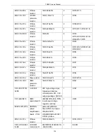
5FE1-BLM41P600SPT
EMI suppression filter
7
L8, L10, L11, FB20, FB22, L14,
L15
5FE1-BLM18PG181SN1
EMI suppression filter
16
FB6, FB7, FB8, FB9, FB10, FB11,
FB12, FB13, FB14, FB15, FB19,
FB21, FB24, FB61, FB33, FB34
2RS1-16-000O
Flake resistor
18
C241, C320, R208, R231, R332,
R213, R217, FB16, R22, R24,
R209, R210, R214, R224, R225,
R94, R107, R109
3FW1-42932-302320
SMD fuse
1
F1
4PE1-16-F5
SMD LED
4
LED2, LED3, LED4, LED5
4PE1-16-F2
SMD LED
1
LED6
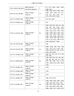
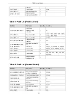
2LG1-NR8040T842-4R7S
SMD power inductor
1
L1
2LG1-SWPA4020-2R2S
SMD power inductor
4
L2, L3, L4, L6
2LW1-16UC-221J
SMD wire winding
inductor
1
L5
2LW1-20UC-180J
SMD wire winding
inductor
2
L7, L33
2LW1-20UC-220J
SMD wire winding
inductor
2
L13, L32
2LW1-16UC-181J
SMD wire winding
inductor
2
L22, L26
2LW1-16UC-221G
SMD wire winding
inductor
1
L24
2LW1-16UC-271G
SMD wire winding
1
L25
159
Summary of Contents for TR850
Page 1: ......
Page 45: ...TR850 Service Manual 5 4 Connection 1 2 3 4 6 8 7 5 9 10 13 14 15 16 18 17 11 12 41 ...
Page 90: ...TR850 Service Manual Figure 1 Rx Module Top Board PCB View 86 ...
Page 91: ...TR850 Service Manual Figure 2 Rx Module Bottom Board PCB View 87 ...
Page 93: ...TR850 Service Manual Figure 5 Power Amplifier Module Bottom Board PCB View 89 ...
Page 94: ...TR850 Service Manual Figure 6 Baseband Mainboard Top Board PCB View 90 ...
Page 95: ...TR850 Service Manual Figure 7 Baseband Mainboard Bottom Board PCB View 91 ...
Page 97: ...TR850 Service Manual Figure 10 Power Board Top Board PCB View 93 ...
Page 114: ...TR850 Service Manual Figure 16 Baseband Mainbaord Schematic Diagram 110 ...
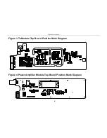
Page 169: ...TR850 Service Manual Figure 1 Rx module Top Board Position Mark Diagram 165 ...
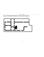
Page 170: ...TR850 Service Manual Figure 2 Rx Module Buttom Board Position Mark Diagram 166 ...
Page 172: ...TR850 Service Manual Figure 5 Power Amplifier Module Buttom Position Mark Diagram 168 ...
Page 173: ...TR850 Service Manual Figure 6 Baseband Mainboard Top Board Position Mark Diagram 169 ...
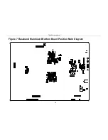
Page 174: ...TR850 Service Manual Figure 7 Baseband Mainboard Buttom Board Position Mark Diagram 170 ...
Page 176: ...TR850 Service Manual Figure 10 Power Board Top Board Position Mark Diagram 172 ...
Page 193: ...TR850 Service Manual Figure 16 Baseband Mainboard Schematic Diagram 189 ...


