TR850 Service Manual
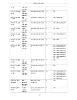
inductor
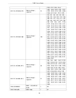
2LI1-1608-R47G
I-shaped inductor
2
L21, L23
2LW1-25UC-681JA
SMD wire winding
inductor
1
L20
1TT1-DTC114YE
SMD triode
18
Q1, Q2, Q5, Q8, Q10, Q12, Q13,
Q14, Q15, Q16, Q17, Q18, Q19,
Q20, Q21, Q22, Q23, Q24
1TT1-MMBT3904
SMD triode
2
Q3, Q9
2RE1-16-49R9
SMD precision resistor
4
R160, R166, R167, R168
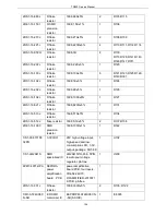
2RE1-16-1001
SMD precision resistor
2
R32, R33
2RE1-16-2001
SMD precision resistor
1
R4
2RS1-16-332J
Flake resistor
4
R179, R293, R294, R363
2RE1-16-4871
SMD precision resistor
1
R172
2RE1-16-8201
SMD precision resistor
1
R18
2RE1-16-1002
SMD precision resistor
3
R1, R120, R121
2RE1-16-4302
SMD precision resistor
2
R13, R366
2RE1-16-18R0
SMD precision resistor
3
R28, R29, R95
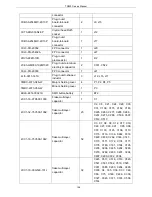
2RS1-16-303J
Flake resistor
1
R5
2RS1-16-100J
Flake resistor
2
R6, R302
2RS1-16-103J
Flake resistor
56
R7, R8, R9, R10, R14, R15, R16,
R17, R19, R20, R21, R23, R25,
R26, R53, R54, R56, R57, R163,
R174, R175, R176, R177, R182,
R183, R186, R187, R188, R189,
R190, R192, R193, R195, R196,
R197, R198, R232, R259, R118, ,
R199, R200, R201, , R206, R211,
R228, R230, R295, R296, R298,
R299, R301, R303, R327, R353,
R355, R367
2RS1-16-510J
Flake resistor
1
R27
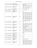
2RS1-16-472J
Flake resistor
10
C260, C261, R133, R134, R138,
R140, R161, R169, R202, R203
2RS1-16-330J
Flake resistor
55
R123, R215, R218, R223, R237,
R238, R239, R240, R241, R242,
R243, R244, R245, R246, R247,
R248, R249, R250, R251, R252,
R254, R279, R280, R281, R282,
R283, R285, R286, R288, R289,
R146, R147, R148, R149, R164,
R165, R171, R207, R229, R291,
R305, R306, R307, R308, R309,
R310, R311, R312, R313, R314,
R315, R348, R350, R362, C296
2RS1-16-101J
Flake resistor
11
R142, R143, R59, R105, R106,
160
Summary of Contents for TR850
Page 1: ......
Page 45: ...TR850 Service Manual 5 4 Connection 1 2 3 4 6 8 7 5 9 10 13 14 15 16 18 17 11 12 41 ...
Page 90: ...TR850 Service Manual Figure 1 Rx Module Top Board PCB View 86 ...
Page 91: ...TR850 Service Manual Figure 2 Rx Module Bottom Board PCB View 87 ...
Page 93: ...TR850 Service Manual Figure 5 Power Amplifier Module Bottom Board PCB View 89 ...
Page 94: ...TR850 Service Manual Figure 6 Baseband Mainboard Top Board PCB View 90 ...
Page 95: ...TR850 Service Manual Figure 7 Baseband Mainboard Bottom Board PCB View 91 ...
Page 97: ...TR850 Service Manual Figure 10 Power Board Top Board PCB View 93 ...
Page 114: ...TR850 Service Manual Figure 16 Baseband Mainbaord Schematic Diagram 110 ...
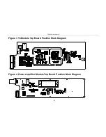
Page 169: ...TR850 Service Manual Figure 1 Rx module Top Board Position Mark Diagram 165 ...
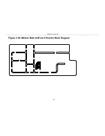
Page 170: ...TR850 Service Manual Figure 2 Rx Module Buttom Board Position Mark Diagram 166 ...
Page 172: ...TR850 Service Manual Figure 5 Power Amplifier Module Buttom Position Mark Diagram 168 ...
Page 173: ...TR850 Service Manual Figure 6 Baseband Mainboard Top Board Position Mark Diagram 169 ...
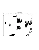
Page 174: ...TR850 Service Manual Figure 7 Baseband Mainboard Buttom Board Position Mark Diagram 170 ...
Page 176: ...TR850 Service Manual Figure 10 Power Board Top Board Position Mark Diagram 172 ...
Page 193: ...TR850 Service Manual Figure 16 Baseband Mainboard Schematic Diagram 189 ...


