TR850 Service Manual
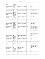
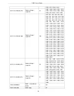
R180, C272, R92, R93, C274,
FB32
2RS1-16-681J
Flake resistor
1
R233
2RS1-16-473J
Flake resistor
2
R119, R300
2RS1-16-102J
Flake resistor
14
R91, R97, R98, R99, , R137,
R156, R157, R158, R159, R219,
R253, R304, R329, R333
2RS1-16-222J
Flake resistor
5
R122, R170, R290, R292, R364
2RS1-16-755J
Flake resistor
1
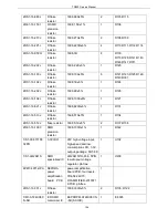
R173
2RS1-16-104J
Flake resistor
1
R205
2RS1-16-471J
Flake resistor
2
R220, R222
2RS1-10-000O
Flake resistor
4
R260, R51, R96, R41
2RS1-10-330J
Flake resistor
26
R64, R73, R74, R75, R76, R78,
R79, R101, R102, R108, R36,
R37, R39, R40, R42, R43, R126,
R127, R135, R136, , R150, R151,
R152, R153, R154, R155
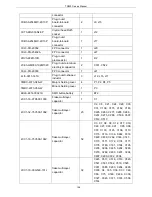
2RS1-10-101J
Flake resistor
3
R103, R104, R111
2RS1-10-472J
Flake resistor
9
R60, R61, R62, R63, R34, R38,
R80, R81, R145
2RS1-10-103J
Flake resistor
21
R45, R46, R47, R48, R49, R50,
R65, R66, R67, R72, R114, R116,
R124, R125, R128, R129, R130,
R131, R132, R204, R115
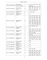
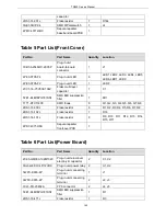
1IS1-TPS54331DDA
SMD switch power IC
1
U1
1IS1-TPS65023
Power management
chip
1
U2
1IS1-LM2941S
SMD specialized IC
1
U3
1IP1-OMAPL138BZWT3
Dual-core CPU
1
U4
1IM1-MT47H64M16
SMD memorizer IC
1
U6
1IM1-K9GAG08U0M-I
SMD memorizer IC
1
U7
1IS1-TPS2051BDGN
LDO power voltage
regulator IC
1
U8
1IS1-RT9193-33PB
SMD voltage
regulator IC
1
U12
1IS1-RT8008GB
SMD voltage reduction
IC
1
U13
1IS1-EP4CE30F23I7N
SMD specialized IC
1
U14
1IS1-RT9193-25PB
SMD voltage
regulator IC
1
U15
1IS1-DP83848I
SMD specialized IC
1
U17
1DR1-TPD4S012DRY
TVS diode
1
U19
1IS1-ADS1015
AD convertor IC
1
U22
1IS1-TLV5614
DA convertor chip
2
U24, U27
1IS1-LM4040B20IDBZT
SMD voltage
1
U29
161
Summary of Contents for TR850
Page 1: ......
Page 45: ...TR850 Service Manual 5 4 Connection 1 2 3 4 6 8 7 5 9 10 13 14 15 16 18 17 11 12 41 ...
Page 90: ...TR850 Service Manual Figure 1 Rx Module Top Board PCB View 86 ...
Page 91: ...TR850 Service Manual Figure 2 Rx Module Bottom Board PCB View 87 ...
Page 93: ...TR850 Service Manual Figure 5 Power Amplifier Module Bottom Board PCB View 89 ...
Page 94: ...TR850 Service Manual Figure 6 Baseband Mainboard Top Board PCB View 90 ...
Page 95: ...TR850 Service Manual Figure 7 Baseband Mainboard Bottom Board PCB View 91 ...
Page 97: ...TR850 Service Manual Figure 10 Power Board Top Board PCB View 93 ...
Page 114: ...TR850 Service Manual Figure 16 Baseband Mainbaord Schematic Diagram 110 ...
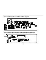
Page 169: ...TR850 Service Manual Figure 1 Rx module Top Board Position Mark Diagram 165 ...
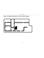
Page 170: ...TR850 Service Manual Figure 2 Rx Module Buttom Board Position Mark Diagram 166 ...
Page 172: ...TR850 Service Manual Figure 5 Power Amplifier Module Buttom Position Mark Diagram 168 ...
Page 173: ...TR850 Service Manual Figure 6 Baseband Mainboard Top Board Position Mark Diagram 169 ...
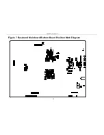
Page 174: ...TR850 Service Manual Figure 7 Baseband Mainboard Buttom Board Position Mark Diagram 170 ...
Page 176: ...TR850 Service Manual Figure 10 Power Board Top Board Position Mark Diagram 172 ...
Page 193: ...TR850 Service Manual Figure 16 Baseband Mainboard Schematic Diagram 189 ...

