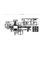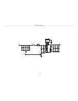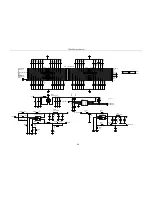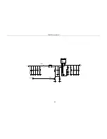
TR850 Service Manual
188
1
2
3
4
5
6
7
8
9
10
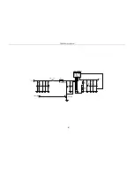
J300
RFAMPCONNECTER
R6043
47K
1
2
3
4
5
6
7
8
9
H4
Hole
C311
101
R304
BLM11A601S
C312
101
1
A0
2
A1
3
A2
4
GND
DATA
5
CLK
6
TEST
7
VCC
8
IC6005
AT24C08
C303
101
C306
101
C302
101
1
2
3
4
5
6
7
8
9
H7
Hole
R311
0R
R300
BLM11A601S
C300
101
C314
101
C316
101
C301
101
C315
101
C317
101
1
2
3
4
5
6
7
8
9
H1
Hole
1
2
3
4
5
6
7
8
9
H8
Hole
R6052
47K
C313
101
C309
101
R6042
47K
1
2
3
4
5
6
7
8
9
H9
Hole
1
2
3
4
5
6
7
8
9
H3
Hole
C307
101
R6053
47K
R301
BLM11A601S
R308
BLM11A601S
R303
BLM11A601S
R309
BLM11A601S
C308
101
R302
BLM11A601S
R305
BLM11A601S
1
2
3
4
5
6
7
8
9
H10
Hole
R6055
NC
R310
BLM11A601S
C305
101
C310
101
NC
R6054
C304
101
1
2
3
4
5
6
7
8
9
H2
Hole
3V3
POWERCONTROL
POWERSWITCH
TXENABLE
SWR-R
TEMPERATURE
SWR-T
DS18B20
EEPROMA0
EEPROMDATA
EEPROMCLK
EEPROMDATA
EEPROMCLK
EEPROMA0
Summary of Contents for TR850
Page 1: ......
Page 45: ...TR850 Service Manual 5 4 Connection 1 2 3 4 6 8 7 5 9 10 13 14 15 16 18 17 11 12 41 ...
Page 90: ...TR850 Service Manual Figure 1 Rx Module Top Board PCB View 86 ...
Page 91: ...TR850 Service Manual Figure 2 Rx Module Bottom Board PCB View 87 ...
Page 93: ...TR850 Service Manual Figure 5 Power Amplifier Module Bottom Board PCB View 89 ...
Page 94: ...TR850 Service Manual Figure 6 Baseband Mainboard Top Board PCB View 90 ...
Page 95: ...TR850 Service Manual Figure 7 Baseband Mainboard Bottom Board PCB View 91 ...
Page 97: ...TR850 Service Manual Figure 10 Power Board Top Board PCB View 93 ...
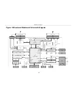
Page 114: ...TR850 Service Manual Figure 16 Baseband Mainbaord Schematic Diagram 110 ...
Page 169: ...TR850 Service Manual Figure 1 Rx module Top Board Position Mark Diagram 165 ...
Page 170: ...TR850 Service Manual Figure 2 Rx Module Buttom Board Position Mark Diagram 166 ...
Page 172: ...TR850 Service Manual Figure 5 Power Amplifier Module Buttom Position Mark Diagram 168 ...
Page 173: ...TR850 Service Manual Figure 6 Baseband Mainboard Top Board Position Mark Diagram 169 ...
Page 174: ...TR850 Service Manual Figure 7 Baseband Mainboard Buttom Board Position Mark Diagram 170 ...
Page 176: ...TR850 Service Manual Figure 10 Power Board Top Board Position Mark Diagram 172 ...
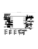
Page 193: ...TR850 Service Manual Figure 16 Baseband Mainboard Schematic Diagram 189 ...


