TR850 Service Manual
23
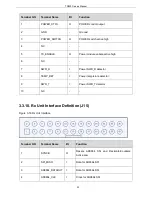
Program_IN_5
Digital Input
High level active Opening
squelch when connected
with Pin20
Digital Input:
(2.5V<VIH<5V,0V<VIL<0.4V)
24
Program_Out_9
(Ext_Alarm)
Reserved
-
25
Aux_Audio_Out1
NULL
-
26
Aux_Audio_Out2
NULL
-
4. Function and Parameter Setting
4.1. Conventional Functions
Conventional DMR functions:
Supports DMR dual slot mode
Supports DMR private call, group calla and all call transfer
Supports short Message, status message transfer
Supports end to end voice and data encryption
Supports GPS
Supports interruption and monitor function
Supports stun, activation, kill signaling transfer
Supports IP connection
Supports Standard AIS Interface
Support Analog and Digital Mode
Supports Pseudo Trunking
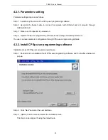
4.2. Parameter Setting
Repeater is set with default parameters when leaving the factory. Parameters such as operation frequency,
channel paramenters, scan and encryption may be changed according to different requirement by
users.Therefore, Kirisun specially designed programmable software CPSp, which is interface-friendly,
easy to operate and display-friendly, to realize the setting for repeater function parameters.
28
Summary of Contents for TR850
Page 1: ......
Page 45: ...TR850 Service Manual 5 4 Connection 1 2 3 4 6 8 7 5 9 10 13 14 15 16 18 17 11 12 41 ...
Page 90: ...TR850 Service Manual Figure 1 Rx Module Top Board PCB View 86 ...
Page 91: ...TR850 Service Manual Figure 2 Rx Module Bottom Board PCB View 87 ...
Page 93: ...TR850 Service Manual Figure 5 Power Amplifier Module Bottom Board PCB View 89 ...
Page 94: ...TR850 Service Manual Figure 6 Baseband Mainboard Top Board PCB View 90 ...
Page 95: ...TR850 Service Manual Figure 7 Baseband Mainboard Bottom Board PCB View 91 ...
Page 97: ...TR850 Service Manual Figure 10 Power Board Top Board PCB View 93 ...
Page 114: ...TR850 Service Manual Figure 16 Baseband Mainbaord Schematic Diagram 110 ...
Page 169: ...TR850 Service Manual Figure 1 Rx module Top Board Position Mark Diagram 165 ...
Page 170: ...TR850 Service Manual Figure 2 Rx Module Buttom Board Position Mark Diagram 166 ...
Page 172: ...TR850 Service Manual Figure 5 Power Amplifier Module Buttom Position Mark Diagram 168 ...
Page 173: ...TR850 Service Manual Figure 6 Baseband Mainboard Top Board Position Mark Diagram 169 ...
Page 174: ...TR850 Service Manual Figure 7 Baseband Mainboard Buttom Board Position Mark Diagram 170 ...
Page 176: ...TR850 Service Manual Figure 10 Power Board Top Board Position Mark Diagram 172 ...
Page 193: ...TR850 Service Manual Figure 16 Baseband Mainboard Schematic Diagram 189 ...


