TR850 Service Manual
spacer, pb-free.
4
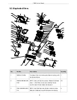
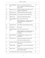
7MBF-4027-02A-X0
DR550 50W duplex bracket, zinc-plated board, 1.5mm
thick, color zinc-plated, pb-free.
1
5
7NHF-040008030-N1
M4*3 hexagonal nut material: iron, internal diameter
M4mm, maximum external diameter 8mm, 3mm thick,
hexagonal nickel-plated nut.
6
6
Duplex, self-purchase
10
7
0ADY-4071-D
STR-U power module, SP-320-12, 12V, 320W, ROHS,
with fan.
1
8
7SAF-030050M-SZY
B-Z1
M3*5 cross round flat head combination machine
screw. Material: hardeded iron,
Φ
3mm*5mm with flat
spacer and spring spacer, pb-free
10
9
3CB1-151007-B
Cable tie holder NYLON 66, 15X10X7, pb-free
10
10
7SAF-040060M-SZH
T-N
M4*6 cross thick head combination machine screw.
4
11
7WOZ-4071-03A
Intermediate board 2, 1mm thick color zinc-plated
board.
1
12
6SS2-4071-HWA
STR-U repeater power board jacking
1
13
7SAF-030080M-SZY
B-Z1
M3*8 cross round flat head combination machine
screw. Material: hardeded iron,
Φ
3mm*8mm, with flat
spacer and spring spacer, pb-free.
28
14
7NHC-055070306-LJ
M3*7+6 Hexagonal Copper Cylinder
19
15
6SS2-4071-HBA
STR-U/V Repeater Base Band Board Jacking
1
16
7MHF-4100-01A-W
TR850 DMR front panel, 5mm thick aluminum
material, oxidized black, laser carving, with copper
cylinder
1
17
7MHP-4071-01-W0
Handle, aluminum, oxidized black
2
18
7MBP-4100-01A-W
TR850 lens 2mmthick, PMMA, transparent, screen
printing
1
37
Summary of Contents for TR850
Page 1: ......
Page 45: ...TR850 Service Manual 5 4 Connection 1 2 3 4 6 8 7 5 9 10 13 14 15 16 18 17 11 12 41 ...
Page 90: ...TR850 Service Manual Figure 1 Rx Module Top Board PCB View 86 ...
Page 91: ...TR850 Service Manual Figure 2 Rx Module Bottom Board PCB View 87 ...
Page 93: ...TR850 Service Manual Figure 5 Power Amplifier Module Bottom Board PCB View 89 ...
Page 94: ...TR850 Service Manual Figure 6 Baseband Mainboard Top Board PCB View 90 ...
Page 95: ...TR850 Service Manual Figure 7 Baseband Mainboard Bottom Board PCB View 91 ...
Page 97: ...TR850 Service Manual Figure 10 Power Board Top Board PCB View 93 ...
Page 114: ...TR850 Service Manual Figure 16 Baseband Mainbaord Schematic Diagram 110 ...
Page 169: ...TR850 Service Manual Figure 1 Rx module Top Board Position Mark Diagram 165 ...
Page 170: ...TR850 Service Manual Figure 2 Rx Module Buttom Board Position Mark Diagram 166 ...
Page 172: ...TR850 Service Manual Figure 5 Power Amplifier Module Buttom Position Mark Diagram 168 ...
Page 173: ...TR850 Service Manual Figure 6 Baseband Mainboard Top Board Position Mark Diagram 169 ...
Page 174: ...TR850 Service Manual Figure 7 Baseband Mainboard Buttom Board Position Mark Diagram 170 ...
Page 176: ...TR850 Service Manual Figure 10 Power Board Top Board Position Mark Diagram 172 ...
Page 193: ...TR850 Service Manual Figure 16 Baseband Mainboard Schematic Diagram 189 ...

