TR850 Service Manual
33
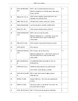
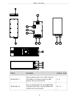
7SAF-030050M-SZY
B-Z1
M3*5 cross round flat head machine screw
Material: hardeded iron, with flat spacer and spring
spacer, pb-free.
10
34
7MBC-4071-01A-W
STR-U power amplifier module big shield cover ,
stainless steel,
0.5mm thick
1
35
7MMC-1943-01A-N
PT8200 power module shield cover; pb-free
1
36
1MR3-RA55H4047M
UHF RF amplifier IC 8200-02, DR550H STU
1
37
6SS2-4071-HPC
STR-U power amplifier jacking (130722)
1
38
7SMF-030060M-SZC
T-N1
M3*6 cross sunk machine screw
Material: hardened iron,
φ
3mm*6mm cross sunk
machine thread, metric coarse thread, black
nickel-plated.
8
39
7MHL-4071-01A-W
STR-U radiator; processed with aluminum alloy
1
40
3CR7-N-KKF1
RF connector
1
41
7SMF-030100M-SZC
T-N1
M3*10 cross sunk machine screw
Material: hardened iron,
φ
3mm*10mm cross sunk
machine thread, metric coarse thread, black
nickel-plated.
12
42
4MF7-DFB602512H
M
Fan DFB602512HM, Specification: 12V/0.3A,
60X60X25mm
1
43
7MHF-4027-02A-Z
DR550 Fan-fixing bracket, zinc-plated board,
0.8mm thick , black dusting on surface
1
44
7STF-050120A-SZHT
-N
M5*12 cross thick head self-tapping screws.
Hardened iron
4
45
7WOZ-4100-04A
Duplex baffle 1mm, thick color zinc-plated board,
dusting
1
46
7WOZ-4100-03A
Rear panel (part no. cancelled) 1.5mm thick color
zinc-plated board, dusting
1
47
7SAF-040100M-SZLJ
M4*10 Cross external hexagonal combination
4
39
Summary of Contents for TR850
Page 1: ......
Page 45: ...TR850 Service Manual 5 4 Connection 1 2 3 4 6 8 7 5 9 10 13 14 15 16 18 17 11 12 41 ...
Page 90: ...TR850 Service Manual Figure 1 Rx Module Top Board PCB View 86 ...
Page 91: ...TR850 Service Manual Figure 2 Rx Module Bottom Board PCB View 87 ...
Page 93: ...TR850 Service Manual Figure 5 Power Amplifier Module Bottom Board PCB View 89 ...
Page 94: ...TR850 Service Manual Figure 6 Baseband Mainboard Top Board PCB View 90 ...
Page 95: ...TR850 Service Manual Figure 7 Baseband Mainboard Bottom Board PCB View 91 ...
Page 97: ...TR850 Service Manual Figure 10 Power Board Top Board PCB View 93 ...
Page 114: ...TR850 Service Manual Figure 16 Baseband Mainbaord Schematic Diagram 110 ...
Page 169: ...TR850 Service Manual Figure 1 Rx module Top Board Position Mark Diagram 165 ...
Page 170: ...TR850 Service Manual Figure 2 Rx Module Buttom Board Position Mark Diagram 166 ...
Page 172: ...TR850 Service Manual Figure 5 Power Amplifier Module Buttom Position Mark Diagram 168 ...
Page 173: ...TR850 Service Manual Figure 6 Baseband Mainboard Top Board Position Mark Diagram 169 ...
Page 174: ...TR850 Service Manual Figure 7 Baseband Mainboard Buttom Board Position Mark Diagram 170 ...
Page 176: ...TR850 Service Manual Figure 10 Power Board Top Board Position Mark Diagram 172 ...
Page 193: ...TR850 Service Manual Figure 16 Baseband Mainboard Schematic Diagram 189 ...


