TR850 Service Manual
-Z1
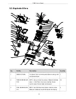
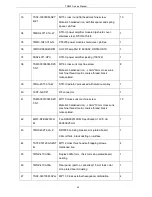
machine screw. Material: hardened iron
48
7MHS-4027-06A-W
M4*8 grounding screw; stainless steel, M4.0*8
1
49
3CR7-SMA-160
RF coaxial line-1 SMA-C-KY1.5-1 to SMA-C-JW1.5,
type: RG141A/U, line length 160mm
1
50
3CR7-BNC-440
BNCcoaxial line SMA-C-J1.5 to BNC(rectangular
flange plate 24*24),RG141A/U, line length: 440mm
1
51
3CP3-YB-B2-Q1
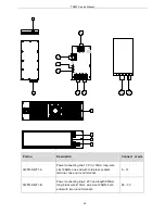
Power socket, 2.5A T 20mm HRC 250V type
1
52
3WPC-WS20K2Z
Two core aviation socket, WS20K2Z
1
53
7NHF-030062025-Z1
M3*2.5 hexagonal nut. Material: iron, internal diameter
M3mm, maximum external diameter 6.2mm, 2.5mm
thick, hexagonal and zinc-plated, metric coarse
thread.
10
54
6SS2-4071-HL1A
STR-U repeater accessory board plug-in material
1
55
3WPC-812028-A
STR-U Network port connecting wire 8pin, wire length
120mm, 28AWG, with network port and crystal head.
1
56
7WOZ-4100-05A
Network port baffle, 1mm thick color zinc-plated board 1
57
7MHL-4071-04A-W
STR-U Tx module aluminum alloy shield bottom cover 1
58
6SS2-4067-HTB
DR650-02 Tx module jacking DR650-02 Tx module
jacking, pb-free
1
59
7MHL-4071-05A-WA
STR-U Tx module aluminum alloy shield up cover
1
40
Summary of Contents for TR850
Page 1: ......
Page 45: ...TR850 Service Manual 5 4 Connection 1 2 3 4 6 8 7 5 9 10 13 14 15 16 18 17 11 12 41 ...
Page 90: ...TR850 Service Manual Figure 1 Rx Module Top Board PCB View 86 ...
Page 91: ...TR850 Service Manual Figure 2 Rx Module Bottom Board PCB View 87 ...
Page 93: ...TR850 Service Manual Figure 5 Power Amplifier Module Bottom Board PCB View 89 ...
Page 94: ...TR850 Service Manual Figure 6 Baseband Mainboard Top Board PCB View 90 ...
Page 95: ...TR850 Service Manual Figure 7 Baseband Mainboard Bottom Board PCB View 91 ...
Page 97: ...TR850 Service Manual Figure 10 Power Board Top Board PCB View 93 ...
Page 114: ...TR850 Service Manual Figure 16 Baseband Mainbaord Schematic Diagram 110 ...
Page 169: ...TR850 Service Manual Figure 1 Rx module Top Board Position Mark Diagram 165 ...
Page 170: ...TR850 Service Manual Figure 2 Rx Module Buttom Board Position Mark Diagram 166 ...
Page 172: ...TR850 Service Manual Figure 5 Power Amplifier Module Buttom Position Mark Diagram 168 ...
Page 173: ...TR850 Service Manual Figure 6 Baseband Mainboard Top Board Position Mark Diagram 169 ...
Page 174: ...TR850 Service Manual Figure 7 Baseband Mainboard Buttom Board Position Mark Diagram 170 ...
Page 176: ...TR850 Service Manual Figure 10 Power Board Top Board Position Mark Diagram 172 ...
Page 193: ...TR850 Service Manual Figure 16 Baseband Mainboard Schematic Diagram 189 ...


