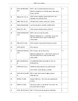
TR850 Service Manual
3WPD-S4071-C
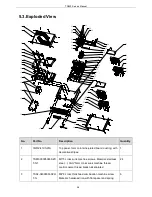
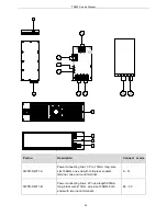
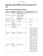
Power connecting line -3 2Pin, 665mm long, wire
size 12AWG
7
—
29
3WPD-S4071-D
Power connecting line -4 2Pin, 315mm long, wire
size 12AWG. One end with two round terminals, and
the other a base.
24
—
35
3WPD-S4071-E
Power connecting line-5 2pin, 575mm long, wire size
18AWG, 3.96 interval, with socket and round
terminal.
18
—
25
3WPD-S4071-F
Power connecting line-6 2pin, wire length 550mm,
wire size 20AWG, interval 2.54, with socket and
cold-press sockets terminal
2
—
26
3CR7-SMA-160
RF coaxial wire-1 SMA-C-KY1.5-1 to SMA-C-JW1.5,
wire type: RG141A/U, wire length 160mm
3
—
13
3CR7-SMA-110A
RF coaxial wire -2 SMA-C-J1.5 to
SMA-C-JW1.5,wire type: RG141A/U, wire length
110mm
15
—
21
3CR7-BNC-440
BNC coaxial wire, SMA-C-J1.5 to BNC(rectangular
flange plate 24*24), RG141A/U, wire length: 440mm
8
—
20
3WPC-812028-A
STR-U internet port connecting wire 8pin, wire length
120mm, 28AWG, with internet port and crystal head,
5
—
9
3WPT-P26050PH25420P
With dual-plugged flat cable AWG26#, 2.54 interval,
wire length 50mm, 20P socket, dual-headed socket
14
—
23
3WPT-P26050PH25426P
With dual-plugged flat cable AWG26#, 2.54 interval,
double flat cable, wire length 50mm, 26Psocket,
dual-headed socket
16
—
19
3WPD-S4071-G
Power connecting line-7 2pin, wire length 350mm,
wire size 20AWG, 2.54 interval, with socket and
cold-press sockets terminal
2
—
27
3CR7-SMA-350
RF coaxial wire -3 SMA-C-JW1.5 to SMA-C-JW1.5,
wire type:RG141A/U, wier length 350mm
22
—
34
3WPT-P26155PH25426P
With three-plugged flat cable, AWG26#, 2.54
interval, three flat cable, 155mm long
4
—
10
43
Summary of Contents for TR850
Page 1: ......
Page 45: ...TR850 Service Manual 5 4 Connection 1 2 3 4 6 8 7 5 9 10 13 14 15 16 18 17 11 12 41 ...
Page 90: ...TR850 Service Manual Figure 1 Rx Module Top Board PCB View 86 ...
Page 91: ...TR850 Service Manual Figure 2 Rx Module Bottom Board PCB View 87 ...
Page 93: ...TR850 Service Manual Figure 5 Power Amplifier Module Bottom Board PCB View 89 ...
Page 94: ...TR850 Service Manual Figure 6 Baseband Mainboard Top Board PCB View 90 ...
Page 95: ...TR850 Service Manual Figure 7 Baseband Mainboard Bottom Board PCB View 91 ...
Page 97: ...TR850 Service Manual Figure 10 Power Board Top Board PCB View 93 ...
Page 114: ...TR850 Service Manual Figure 16 Baseband Mainbaord Schematic Diagram 110 ...
Page 169: ...TR850 Service Manual Figure 1 Rx module Top Board Position Mark Diagram 165 ...
Page 170: ...TR850 Service Manual Figure 2 Rx Module Buttom Board Position Mark Diagram 166 ...
Page 172: ...TR850 Service Manual Figure 5 Power Amplifier Module Buttom Position Mark Diagram 168 ...
Page 173: ...TR850 Service Manual Figure 6 Baseband Mainboard Top Board Position Mark Diagram 169 ...
Page 174: ...TR850 Service Manual Figure 7 Baseband Mainboard Buttom Board Position Mark Diagram 170 ...
Page 176: ...TR850 Service Manual Figure 10 Power Board Top Board Position Mark Diagram 172 ...
Page 193: ...TR850 Service Manual Figure 16 Baseband Mainboard Schematic Diagram 189 ...

