TR850 Service Manual
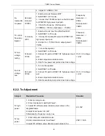
integrated tester.
4. Adjust to test power: 20W.
5. Modulate the frequency one by one.
Low
frequency
modulation
frequency
deviation
1. Enter computer modulation mode.
2. Click frequency F1 to F6.
3. When AF Freq is 0.1kHz, observe FM Deviation on the
integrated tester, and modulate PC software value.
4. Adjust FM Deviation to 5.0
±
0.05kHz.
5. Click “ok” to save.
4.95kHz-5.05kHz
High
frequency
modulation
frequency
deviation
1. Enter computer modulation mode.
2. Click Frequency F1 to F6.
3. When AF Freq is 6.0 kHz, observe FM Deviation on the
integrated tester, and modulate PC software value.
4. modulate FM Deviationto5.0
±
0.05kHz.
5. Click “ok” to save.
4.95kHz-5.05kHz
4FSK EER
test
1. Enter computer modulation mode.
2. Modulate PC software value to make repeater transmit
O.153.
3. Check 4FSK EER
≤
5%.
4. Modulate frequenciesone by one.
5. Observe FSK EER value on the integrated tester.
6. Check 4FSK EER
≤
5%.
FSK EER
≤
5%
Maximum
audio
frequency
deviation
test.
1. Connect the audio input wire to repeater.
2. Output audio signal 1KHz RMS 120mV to repeater and make it
transmit.
3. The audio frequency deviation should be: N: 2000
±
100Hz,
W:4000
±
100Hz.
4. Test frequencies one by one.
N: 2000
±
200Hz
W: 4000
±
400Hz
QT/DQT
frequency
deviation
and wave
form test.
1. Observe frequency deviation of QT.
2. Observe frequency deviation and wave form of DQT.
N: 350
±
150Hz
W: 750
±
250Hz
Modulationdi
stortion
Observe distortion form value.
<
3%
Tx SNR
Observe SNR form value
W:
>
45dB
N:
>
40dB
46
Summary of Contents for TR850
Page 1: ......
Page 45: ...TR850 Service Manual 5 4 Connection 1 2 3 4 6 8 7 5 9 10 13 14 15 16 18 17 11 12 41 ...
Page 90: ...TR850 Service Manual Figure 1 Rx Module Top Board PCB View 86 ...
Page 91: ...TR850 Service Manual Figure 2 Rx Module Bottom Board PCB View 87 ...
Page 93: ...TR850 Service Manual Figure 5 Power Amplifier Module Bottom Board PCB View 89 ...
Page 94: ...TR850 Service Manual Figure 6 Baseband Mainboard Top Board PCB View 90 ...
Page 95: ...TR850 Service Manual Figure 7 Baseband Mainboard Bottom Board PCB View 91 ...
Page 97: ...TR850 Service Manual Figure 10 Power Board Top Board PCB View 93 ...
Page 114: ...TR850 Service Manual Figure 16 Baseband Mainbaord Schematic Diagram 110 ...
Page 169: ...TR850 Service Manual Figure 1 Rx module Top Board Position Mark Diagram 165 ...
Page 170: ...TR850 Service Manual Figure 2 Rx Module Buttom Board Position Mark Diagram 166 ...
Page 172: ...TR850 Service Manual Figure 5 Power Amplifier Module Buttom Position Mark Diagram 168 ...
Page 173: ...TR850 Service Manual Figure 6 Baseband Mainboard Top Board Position Mark Diagram 169 ...
Page 174: ...TR850 Service Manual Figure 7 Baseband Mainboard Buttom Board Position Mark Diagram 170 ...
Page 176: ...TR850 Service Manual Figure 10 Power Board Top Board Position Mark Diagram 172 ...
Page 193: ...TR850 Service Manual Figure 16 Baseband Mainboard Schematic Diagram 189 ...


