TR850 Service Manual
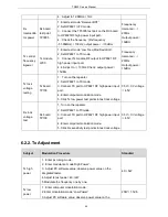
Rx distortion
Observe the distortion value,
<
3%
Rx SNR
Observe SNR value
W:
>
45dB
N:
>
40dB
CTCSS/CDC
SS
-
Can transmit
BER Test
1. Set the output range of 3920 as -118dBm.
2. Enter BER test mode.
3. Click “Start”, and observe BER.
EER
≤
5%
7. Main Technical Functions and Specifications
General Specification
Frequency Range
UHF: 400-470MHz VHF:136-174MHz
Channel Capacity
16
Channel Spacing
12.5kHz/20kHz/25kHz
Weight
11.5kg
Dimension(H*B*D)
138mm*62mm*38mm
Environment Index
Operating
Temperature
-30
℃
~+60
℃
Storage Temperature
-40
℃
~+85
℃
Rx Parameter
Frequency Stability
±
1.5ppm
Analog Rx Sensitivity
-118dBm(12dB)/-121dBm(12dB)
Digital Rx Sensitivity
-120dBm(5%)
Intermodulation
ETSI: 70dB TIA603: 75dB
49
Summary of Contents for TR850
Page 1: ......
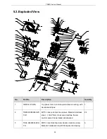
Page 45: ...TR850 Service Manual 5 4 Connection 1 2 3 4 6 8 7 5 9 10 13 14 15 16 18 17 11 12 41 ...
Page 90: ...TR850 Service Manual Figure 1 Rx Module Top Board PCB View 86 ...
Page 91: ...TR850 Service Manual Figure 2 Rx Module Bottom Board PCB View 87 ...
Page 93: ...TR850 Service Manual Figure 5 Power Amplifier Module Bottom Board PCB View 89 ...
Page 94: ...TR850 Service Manual Figure 6 Baseband Mainboard Top Board PCB View 90 ...
Page 95: ...TR850 Service Manual Figure 7 Baseband Mainboard Bottom Board PCB View 91 ...
Page 97: ...TR850 Service Manual Figure 10 Power Board Top Board PCB View 93 ...
Page 114: ...TR850 Service Manual Figure 16 Baseband Mainbaord Schematic Diagram 110 ...
Page 169: ...TR850 Service Manual Figure 1 Rx module Top Board Position Mark Diagram 165 ...
Page 170: ...TR850 Service Manual Figure 2 Rx Module Buttom Board Position Mark Diagram 166 ...
Page 172: ...TR850 Service Manual Figure 5 Power Amplifier Module Buttom Position Mark Diagram 168 ...
Page 173: ...TR850 Service Manual Figure 6 Baseband Mainboard Top Board Position Mark Diagram 169 ...
Page 174: ...TR850 Service Manual Figure 7 Baseband Mainboard Buttom Board Position Mark Diagram 170 ...
Page 176: ...TR850 Service Manual Figure 10 Power Board Top Board Position Mark Diagram 172 ...
Page 193: ...TR850 Service Manual Figure 16 Baseband Mainboard Schematic Diagram 189 ...


