TR850 Service Manual
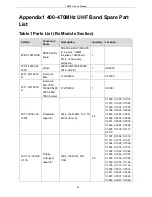
Appendix1 400-470MHz UHF Band Spare Part
List
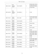
Table1 Parts List (Rx Module Section)
Part No.
Accessory
Name
Description
Quantity
Location
6PM7-4067-HRB
DR650-02 Rx
board
DR650-02-RX-130304.PC
B, 4 layers, 1.6MM
thickness, 194X90mm,
FR-4, no frequency
distinction
1
3FW1-42932-30
2320
R fuse
429003/433003/466003,
3216, 3A/32V
1
CB5000
5FT1-LTWC450
G
E ceramic
filter
LTWC450G
1
CF3000
5FT1-LTWC450
H
E ceramic
filter 7200
7200EX 5200
6500, 6800,
7800, helmet
LTWC450H
1
CF3001
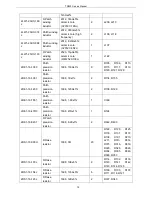
2CT1-TS32-160-
100M
R tantalum
capacitor
3216,
10μF±20%, 16V, TS
series (level A)
28
C1000, C1005, C1014,
C1019, C1020, C1025,
C1030, C1031, C1057,
C1058, C4024, C4029,
C4040, C4045, C4047,
C4052, C6002, C6008,
C6011, C3029, C3030,
C3046, C3067, C3094,
C3097, C3109, C3112,
C3113
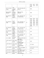
2CC1-16-C0G50
0-101J
R flake
multi-layer
capacitor
1608, 100P±5%, 50V,
C0G
60
C1001, C1004, C1010,
C1015, C1018, C1021,
C1024, C1026, C1029,
C1034, C1035, C1037,
C1039, C1042, C1044,
C1046, C1049, C1051,
C1053, C1056, C1059,
C1063, C1064, C1104,
C1105, C1112, C1119,
C2008, C2010, C2012,
C2017, C3003, C3004,
C3027, C3031, C3040,
C3042, C3047, C3082,
55
Summary of Contents for TR850
Page 1: ......
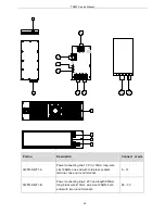
Page 45: ...TR850 Service Manual 5 4 Connection 1 2 3 4 6 8 7 5 9 10 13 14 15 16 18 17 11 12 41 ...
Page 90: ...TR850 Service Manual Figure 1 Rx Module Top Board PCB View 86 ...
Page 91: ...TR850 Service Manual Figure 2 Rx Module Bottom Board PCB View 87 ...
Page 93: ...TR850 Service Manual Figure 5 Power Amplifier Module Bottom Board PCB View 89 ...
Page 94: ...TR850 Service Manual Figure 6 Baseband Mainboard Top Board PCB View 90 ...
Page 95: ...TR850 Service Manual Figure 7 Baseband Mainboard Bottom Board PCB View 91 ...
Page 97: ...TR850 Service Manual Figure 10 Power Board Top Board PCB View 93 ...
Page 114: ...TR850 Service Manual Figure 16 Baseband Mainbaord Schematic Diagram 110 ...
Page 169: ...TR850 Service Manual Figure 1 Rx module Top Board Position Mark Diagram 165 ...
Page 170: ...TR850 Service Manual Figure 2 Rx Module Buttom Board Position Mark Diagram 166 ...
Page 172: ...TR850 Service Manual Figure 5 Power Amplifier Module Buttom Position Mark Diagram 168 ...
Page 173: ...TR850 Service Manual Figure 6 Baseband Mainboard Top Board Position Mark Diagram 169 ...
Page 174: ...TR850 Service Manual Figure 7 Baseband Mainboard Buttom Board Position Mark Diagram 170 ...
Page 176: ...TR850 Service Manual Figure 10 Power Board Top Board Position Mark Diagram 172 ...
Page 193: ...TR850 Service Manual Figure 16 Baseband Mainboard Schematic Diagram 189 ...


