TR850 Service Manual
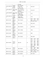
2RE1-16-1000
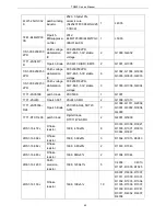
Patch
precision
resistor
1608,
100Ω±1%
11
R3002, R3003, R1020,
R1008, R1009, R1010,
R1013, R1014, R1016,
R1022, R1024
2RE1-16-47R0
Patch
precision
resistor
1608,
47Ω±1%
1
R1019
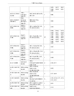
2RS1-16-102J
R flake
resistor
1608, 1K±5%
7
R1023, R1028, R1042,
R3018, R3036, R4004,
R4009
2RS1-16-124J
R flake
resistor
1608, 120K±5%
1
R1026
2RS1-16-822J
R flake
resistor
1608, 8.2K±5%
2
R2007, R5003
2RS1-16-270J
R flake
resistor
1608,
27Ω±5%
1
R2009
2RS1-16-221J
R flake
resistor
1608,
220Ω±5%
2
R2011, R2012
2RS1-16-510J
R flake
resistor
1608,
51Ω±5%
1
R2018
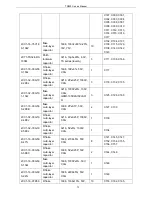
2RS1-16-104J
R flake
resistor
1608, 100K±5%
13
R3005, R3006, R3007,
R3008, R3009, R3010,
R3011, R3012, R3013,
R3014, R3015, R3016,
R4006
2RS1-16-821J
R flake
resistor
1608,
820Ω±5%
1
R3022
2RS1-16-473J
R flake
resistor
1608, 47K±5%
8
R3023, R3025, R5000,
R5001, R6042, R6043,
R6052, R6053
2RS1-16-182J
R flake
resistor
1608, 1.8K±5%
2
R3024, R3026
2RS1-16-363J
R flake
resistor
1608, 36K±5%
2
R3030, R3032
2RS1-16-223J
R flake
resistor
1608, 22K±5%
4
R3039, R3040, R3045,
R3046
63
Summary of Contents for TR850
Page 1: ......
Page 45: ...TR850 Service Manual 5 4 Connection 1 2 3 4 6 8 7 5 9 10 13 14 15 16 18 17 11 12 41 ...
Page 90: ...TR850 Service Manual Figure 1 Rx Module Top Board PCB View 86 ...
Page 91: ...TR850 Service Manual Figure 2 Rx Module Bottom Board PCB View 87 ...
Page 93: ...TR850 Service Manual Figure 5 Power Amplifier Module Bottom Board PCB View 89 ...
Page 94: ...TR850 Service Manual Figure 6 Baseband Mainboard Top Board PCB View 90 ...
Page 95: ...TR850 Service Manual Figure 7 Baseband Mainboard Bottom Board PCB View 91 ...
Page 97: ...TR850 Service Manual Figure 10 Power Board Top Board PCB View 93 ...
Page 114: ...TR850 Service Manual Figure 16 Baseband Mainbaord Schematic Diagram 110 ...
Page 169: ...TR850 Service Manual Figure 1 Rx module Top Board Position Mark Diagram 165 ...
Page 170: ...TR850 Service Manual Figure 2 Rx Module Buttom Board Position Mark Diagram 166 ...
Page 172: ...TR850 Service Manual Figure 5 Power Amplifier Module Buttom Position Mark Diagram 168 ...
Page 173: ...TR850 Service Manual Figure 6 Baseband Mainboard Top Board Position Mark Diagram 169 ...
Page 174: ...TR850 Service Manual Figure 7 Baseband Mainboard Buttom Board Position Mark Diagram 170 ...
Page 176: ...TR850 Service Manual Figure 10 Power Board Top Board Position Mark Diagram 172 ...
Page 193: ...TR850 Service Manual Figure 16 Baseband Mainboard Schematic Diagram 189 ...


