TR850 Service Manual
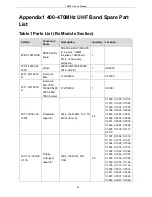
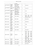
62/65/68/DR5
5/DM58/3208/
V68/E66
DP77/CD37/RD47/AP57
2LW1-20UC-120
J
patch winding
inductor
2012, 12nH±5%, ceramic
core (C2012C-12NJ)
1
L1016
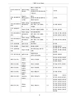
1DV1-1SV305
R patch
varactor
1SV305
8
D1002, D1003, D1004,
D1005, D1006, D1007,
D1008, D1009
2LW1-16UC-180
J
R patch
winding
inductor
1608, 18nH±5%, ceramic
core (C1608CB-18NJ)
1
L1013
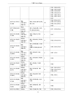
2LL1-16-R22K
R laminated
inductor
1608,
0.22μH±10%(MLF1608D
R22K TA00)
1
L3017
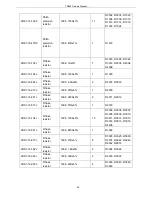
2CC1-16-C0G50
0-151J
R flake
multi-layer
capacitor
1608, 150P±5%, 50V,
C0G
1
C3058
2RS1-16-561J
R flake
resistors
1608,
560Ω±5%
1
R4005
2CC1-16-C0G50
0-2R5B
R R flake
multi-layer
resistor
1608, 2.5P/2.4P±0.1P,
50V, C0G
1
C1073
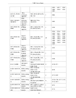
2LW1-20UC-180
G
patch winding
inductor
ceramic core
LQW2UAS18NG00 0805
18nH±2%
1
L1017
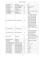
2CC1-16-C0G50
0-3R0B
flake
multi-layer
capacitor
1608, 3P±0.1P, 50V, C0G
2
C3002, C2018
2RS1-16-820J
flake resistor
1608,
82Ω±5%
1
R3000
3CR7-SMA-50K
WE-2
RF coaxial
connector
SMA-50KWE-2, 5PIN, 90
degrees,23mm long. pitch:
2.54mm
2
J3000, J3002
3CB3-A2548WV-
2X13P
Board-board
connector
2*13 socket, 180 degrees,
spacing 2.54mm,
40.64X9X9.1mm,
manufacturer: JOINT
TECH
1
J6000
Table2 Parts List (Tx Module Section)
Part No.
Acccessory
Names
Description
Quantity
Location
3FW1-42932-30
2320
R patch fuse
429003/433003/466003,
3216, 3A/32V
1
CB400
65
Summary of Contents for TR850
Page 1: ......
Page 45: ...TR850 Service Manual 5 4 Connection 1 2 3 4 6 8 7 5 9 10 13 14 15 16 18 17 11 12 41 ...
Page 90: ...TR850 Service Manual Figure 1 Rx Module Top Board PCB View 86 ...
Page 91: ...TR850 Service Manual Figure 2 Rx Module Bottom Board PCB View 87 ...
Page 93: ...TR850 Service Manual Figure 5 Power Amplifier Module Bottom Board PCB View 89 ...
Page 94: ...TR850 Service Manual Figure 6 Baseband Mainboard Top Board PCB View 90 ...
Page 95: ...TR850 Service Manual Figure 7 Baseband Mainboard Bottom Board PCB View 91 ...
Page 97: ...TR850 Service Manual Figure 10 Power Board Top Board PCB View 93 ...
Page 114: ...TR850 Service Manual Figure 16 Baseband Mainbaord Schematic Diagram 110 ...
Page 169: ...TR850 Service Manual Figure 1 Rx module Top Board Position Mark Diagram 165 ...
Page 170: ...TR850 Service Manual Figure 2 Rx Module Buttom Board Position Mark Diagram 166 ...
Page 172: ...TR850 Service Manual Figure 5 Power Amplifier Module Buttom Position Mark Diagram 168 ...
Page 173: ...TR850 Service Manual Figure 6 Baseband Mainboard Top Board Position Mark Diagram 169 ...
Page 174: ...TR850 Service Manual Figure 7 Baseband Mainboard Buttom Board Position Mark Diagram 170 ...
Page 176: ...TR850 Service Manual Figure 10 Power Board Top Board Position Mark Diagram 172 ...
Page 193: ...TR850 Service Manual Figure 16 Baseband Mainboard Schematic Diagram 189 ...


