TR850 Service Manual
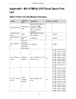
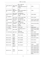
TA
SOT23
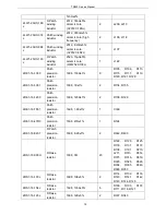
2CC1-16-C0G50
0-100D
R flake
multi-layer
capacitor
1608, 10P±0.5P, 50V,
C0G
2
C188, C189
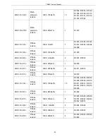
2CC1-16-C0G50
0-101J
R flake
multi-layer
capacitor
1608, 100P±5%, 50V,
C0G
64
C161,
C166,
C167,
C182,
C184,
C186,
C199,
C208,
C212,
C214,
C216,
C224,
C228,
C234,
C239,
C242,
C246,
C255,
C289,
C291,
C295,
C297,
C300,
C301,
C302,
C303,
C304,
C305,
C306,
C307,
C308,
C309,
C310,
C311,
C312,
C315,
C316,
C317,
C320,
C321,
C322,
C323,
C340,
C341,
C344,
C345,
C102,
C106,
C111,
C113,
C117,
C119,
C123,
C124,
C138,
C140,
C142,
C144,
C146,
C150,
C151,
C153,
C157,
C160,
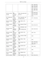
2CC1-16-C0G50
0-102J
flake
multi-layer
capacitor
1608, 1000P±5%, 50V,
C0G
8
C175,
C240,
C325,
C329,
C332,
C334,
C342, R333
2CC1-16-C0G50
0-120J
R flake
multi-layer
capacitor
1608, 12P±5%, 50V,
C0G
3
C131, C132, C230
2CC1-16-C0G50
0-121J
R flake
multi-layer
capacitor
1608, 120P±5%, 50V,
C0G
1
C244
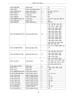
2CC1-16-C0G50
0-180J
R flake
multi-layer
capacitor
1608, 18P±5%, 50V,
C0G
1
C171
2CC1-16-C0G50
0-1R0B
flake
multi-layer
capacitor
1608, 1P±0.1P, 50V,
C0G
10
C129,
C133,
C135,
C169,
C177,
C179,
C313,
C314,
C318,
C319
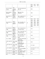
2CC1-16-C0G50
0-430J
R flake
multi-layer
capacitor
1608, 43P±5%, 50V,
C0G
1
C221
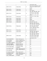
2CC1-16-C0G50
R flake
1608, 47P±5%, 50V,
2
C220, C256
67
Summary of Contents for TR850
Page 1: ......
Page 45: ...TR850 Service Manual 5 4 Connection 1 2 3 4 6 8 7 5 9 10 13 14 15 16 18 17 11 12 41 ...
Page 90: ...TR850 Service Manual Figure 1 Rx Module Top Board PCB View 86 ...
Page 91: ...TR850 Service Manual Figure 2 Rx Module Bottom Board PCB View 87 ...
Page 93: ...TR850 Service Manual Figure 5 Power Amplifier Module Bottom Board PCB View 89 ...
Page 94: ...TR850 Service Manual Figure 6 Baseband Mainboard Top Board PCB View 90 ...
Page 95: ...TR850 Service Manual Figure 7 Baseband Mainboard Bottom Board PCB View 91 ...
Page 97: ...TR850 Service Manual Figure 10 Power Board Top Board PCB View 93 ...
Page 114: ...TR850 Service Manual Figure 16 Baseband Mainbaord Schematic Diagram 110 ...
Page 169: ...TR850 Service Manual Figure 1 Rx module Top Board Position Mark Diagram 165 ...
Page 170: ...TR850 Service Manual Figure 2 Rx Module Buttom Board Position Mark Diagram 166 ...
Page 172: ...TR850 Service Manual Figure 5 Power Amplifier Module Buttom Position Mark Diagram 168 ...
Page 173: ...TR850 Service Manual Figure 6 Baseband Mainboard Top Board Position Mark Diagram 169 ...
Page 174: ...TR850 Service Manual Figure 7 Baseband Mainboard Buttom Board Position Mark Diagram 170 ...
Page 176: ...TR850 Service Manual Figure 10 Power Board Top Board Position Mark Diagram 172 ...
Page 193: ...TR850 Service Manual Figure 16 Baseband Mainboard Schematic Diagram 189 ...


