TR850 Service Manual
pb-free
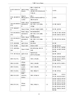
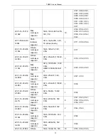
2RS1-16-471J
R flake
resistor
1608,
470Ω±5%
1
L111
2LH1-R903R0-L
11-05
R patch air
core inductor
wire diameter
φ0.9,
internal diameter
φ3.0, 11
circles, pin height
0.5mm, back-roll
1
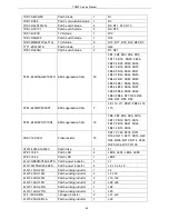
L112
2LL1-16-47NJ
R Laminated
inductor
1608,
47nH±5%(MLG1608B47
NJ)
2
L114, L115
5FE1-BLM21P30
0S
R patch EMI
suppression
filte
2012,
BLM21P300S/BLM21PG
300S(0149-05)
1
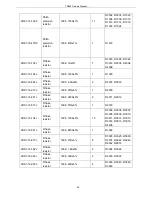
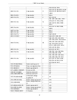
L200
1TT1-FMMT717
TA
R patch triode
FMMT717A, PNP,
SOT23
2
Q100, Q103
1TT1-DTC114YE patch triode
Digital triode
DTC114YE-SMD
3
Q101, Q104, Q200
1TT1-2SC3357
R patch triode
2SC3357(RE),
SOT89(NEC)
1
Q102
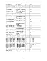
2RS1-16-473J
R Flake
resistor
1608, 47K±5%
9
R100, R118, R133,
R200, R201, R6042,
R6043, R6052, R6053
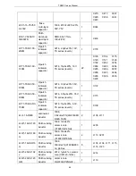
2RS1-16-561J
R Flake
resistor
1608,
560Ω±5%
2
R101, R119
2RE1-16-8201
R patch
precision
resistor
1608, 8.2K±1%
2
R102, R203
2RS1-16-820J
Flake resistor
1608,
82Ω±5%
2
R105, R115
2RE1-16-1501
R patch
precision
resistor
1608, 1.5K±1%
1
R106
2RS1-16-270J
R Flake
resistor
1608,
27Ω±5%
2
R108, R109
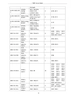
2RS1-16-221J
R Flake
resistor
1608,
220Ω±5%
4
R110, R111, R112,
R114
2RS1-16-000O
R Flake
resistor
1608,
0Ω
8
R130, R141, R113,
R128, R143, R146,
R147, R311
2RS1-16-222J
R Flake
resistor
1608, 2.2K±5%
1
R120
2RS1-16-103J
R Flake
resistor
1608, 10K±5%
7
R121, R122, R123,
R124, R125, R129,
R307
2RS1-16-202J
R Flake
resistor
1608, 2K±5%
1
R126
2RS1-16-104J
R Flake
1608, 100K±5%
1
R127
75
Summary of Contents for TR850
Page 1: ......
Page 45: ...TR850 Service Manual 5 4 Connection 1 2 3 4 6 8 7 5 9 10 13 14 15 16 18 17 11 12 41 ...
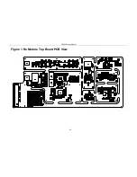
Page 90: ...TR850 Service Manual Figure 1 Rx Module Top Board PCB View 86 ...
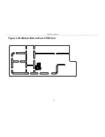
Page 91: ...TR850 Service Manual Figure 2 Rx Module Bottom Board PCB View 87 ...
Page 93: ...TR850 Service Manual Figure 5 Power Amplifier Module Bottom Board PCB View 89 ...
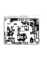
Page 94: ...TR850 Service Manual Figure 6 Baseband Mainboard Top Board PCB View 90 ...
Page 95: ...TR850 Service Manual Figure 7 Baseband Mainboard Bottom Board PCB View 91 ...
Page 97: ...TR850 Service Manual Figure 10 Power Board Top Board PCB View 93 ...
Page 114: ...TR850 Service Manual Figure 16 Baseband Mainbaord Schematic Diagram 110 ...
Page 169: ...TR850 Service Manual Figure 1 Rx module Top Board Position Mark Diagram 165 ...
Page 170: ...TR850 Service Manual Figure 2 Rx Module Buttom Board Position Mark Diagram 166 ...
Page 172: ...TR850 Service Manual Figure 5 Power Amplifier Module Buttom Position Mark Diagram 168 ...
Page 173: ...TR850 Service Manual Figure 6 Baseband Mainboard Top Board Position Mark Diagram 169 ...
Page 174: ...TR850 Service Manual Figure 7 Baseband Mainboard Buttom Board Position Mark Diagram 170 ...
Page 176: ...TR850 Service Manual Figure 10 Power Board Top Board Position Mark Diagram 172 ...
Page 193: ...TR850 Service Manual Figure 16 Baseband Mainboard Schematic Diagram 189 ...


