TR850 Service Manual
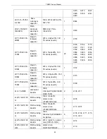
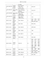
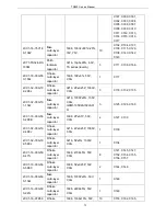
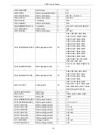
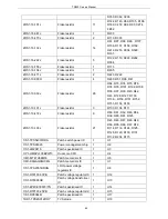
1IS1-ADS1015
AD transformer IC
1
U22
1IS1-TLV5614
DA transformer chip
2
U24, U27
1IS1-LM4040B20IDBZT
Patch voltage regulator IC
1
U29
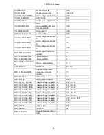
1IS1-TLV320AIC14
CODEC chip
1
U30
1IS1-TDA8541T
Audio power amplifier IC
1
U31
1IS1-MAX3232ESE
Patch
dual-channelRS-232 wire
driver/receiver IC
1
U32
1IL1-AD8031ARTZ
Patch linear IC
1
U38
1IM1-AT24C08CN-SH
memorizer IC
1
U23
1IS1-XC6209F302PR
Patch voltage stabilization
IC
1
U20
1IS1-XC6209F332PR
Patch voltage stabilization
IC
1
U5
1IS1-XC6209F502PR
Patch voltage stabilization
IC
1
U26
5XT1-MC146-32R76K
Patch ceramic harmonic
oscillator
1
Y1
5OC1-24R0-MML-3225
crystal oscillator
1
Y2
5OC1-50R0-MML-3225
crystal oscillator
1
Y3
5XC1-18R4-CEC5032SC
H
Patch crystal oscillator
1
Y4
1TF1-ST2301
Patch FET
2
Q7, Q11
5OD1-12R8-AL3-3225
Pressure temperature
compensated crystal
oscillator
1
Y5
1MR3-MAX-6Q
GPS module
1
U9
2RE1-16-1801
Patch precision resistor
1
R365
2CC1-32-Y5V160-106Z
Flake multi-layer capacitor 2
C243, C237
2CC1-16-C0G500-7R0C
Flake multi-layer capacitor 2
C310, C328
2CC1-16-C0G500-9R0C
Flake multi-layer capacitor 2
C311, C445
2CC1-16-C0G500-150J
Flake multi-layer capacitor 2
C312, C329
2CC1-16-C0G500-240J
Flake multi-layer capacitor 2
C314, C446
2CC1-16-C0G500-390J
Flake multi-layer capacitor 2
C313, C330
2CC1-16-C0G500-820J
Flake multi-layer capacitor 3
C301, C303, C307
2CC1-16-C0G500-121J
Flake multi-layer capacitor 1
C308
2CC1-16-C0G500-151J
Flake multi-layer capacitor 1
C305
2RS1-16-301J
Flake resistor
1
R144
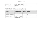
3SE1-SDIP-04
Patch DIP
1
J4
6PM7-4071-HBC
Repeater baseband board
PCB
1
83
Summary of Contents for TR850
Page 1: ......
Page 45: ...TR850 Service Manual 5 4 Connection 1 2 3 4 6 8 7 5 9 10 13 14 15 16 18 17 11 12 41 ...
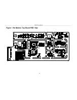
Page 90: ...TR850 Service Manual Figure 1 Rx Module Top Board PCB View 86 ...
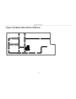
Page 91: ...TR850 Service Manual Figure 2 Rx Module Bottom Board PCB View 87 ...
Page 93: ...TR850 Service Manual Figure 5 Power Amplifier Module Bottom Board PCB View 89 ...
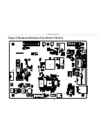
Page 94: ...TR850 Service Manual Figure 6 Baseband Mainboard Top Board PCB View 90 ...
Page 95: ...TR850 Service Manual Figure 7 Baseband Mainboard Bottom Board PCB View 91 ...
Page 97: ...TR850 Service Manual Figure 10 Power Board Top Board PCB View 93 ...
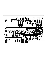
Page 114: ...TR850 Service Manual Figure 16 Baseband Mainbaord Schematic Diagram 110 ...
Page 169: ...TR850 Service Manual Figure 1 Rx module Top Board Position Mark Diagram 165 ...
Page 170: ...TR850 Service Manual Figure 2 Rx Module Buttom Board Position Mark Diagram 166 ...
Page 172: ...TR850 Service Manual Figure 5 Power Amplifier Module Buttom Position Mark Diagram 168 ...
Page 173: ...TR850 Service Manual Figure 6 Baseband Mainboard Top Board Position Mark Diagram 169 ...
Page 174: ...TR850 Service Manual Figure 7 Baseband Mainboard Buttom Board Position Mark Diagram 170 ...
Page 176: ...TR850 Service Manual Figure 10 Power Board Top Board Position Mark Diagram 172 ...
Page 193: ...TR850 Service Manual Figure 16 Baseband Mainboard Schematic Diagram 189 ...

