background image

R1040 MAINTENANCE MANUAL 

Page 37 of 48 


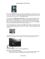
                Fig 5.6.2 


Similarly,  check  the  valve  clearance  of  exhaust  valve  with  0.3mm  feeler  gauge. 
Readjust if necessary.  


Check the valve clearances of each of the remaining cylinders and readjust, if  necessary


Do not change the setting of oil metering screw unless required. With hot engine 
running at idling, an  oil  flow  to  pad  at  rocker  arm  must  be  just noticeable. An 
excess oil flow can lead to higher oil consumption. 

5.7


Maintenance of Electrical Equipment 


5.7.1


Starter Motor 


Ensure that the mounting bolts are securely fastened and all electrical connections are clean 
and tight.  Cables should be examined for fractures, particularly where the strands enter the 
terminal lugs. 


 Check the brushes. They must be renewed if worn to approximately 10 mm (for 2 & 

        3 cylinder engines, and 13mm (for 4 & 6 cylinder engines, which is half of the original 

or to a point where springs no longer provide effective pressure.  


 Brushes must always be replaced in sets and with the correct grade. 


Check  the brush spring  balance  as shown in F ig.5.7.1. The  spring  pressure      
should be as follows- 


                 Fig 5.7.1 


       0.965 to 1 -080kg (for 2 & 3 cylinder engines) 


       1.220 to 1.580 kg (for 4 & 6 cylinder engines)  


If the pressure is not within the above   limits, renew the springs in set and not 

individually. 


Summary of Contents for 2R1040

Page 1: ...ntenance 21 5 1 Maintenance of Lubrication system 21 27 5 2 Maintenance of Fuel System 28 5 3 Maintenance of Cooling System 29 30 5 4 Maintenance of Dry type air cleaner 31 34 5 5 Belt drives 35 5 6 A...

Page 2: ...g out maintenance or repair work When the work is complete be sure to install safety devices that may have been removed If you have to work on a running engine ensure that all clothing is tight fittin...

Page 3: ...ts can be more easily dealt with 2 2 3 Model Designation The engine model is punched on nameplate in column TYPE The information about engine series No off cylinders Piston displacement in liter per c...

Page 4: ...Filter 19 Engine mounting foot Flywheel end side 8 Dipstick 20 Exhaust manifold 9 Lube oil sump with drain Plug 21 Rocker cover 10 Gear casing 22 Flywheel housing 11 Radiator 23 Flywheel 12 Balance Wa...

Page 5: ...icated Piston cooling nozzles are provided for piston cooling for turbocharged engines only Oil supply to valve gear is achieved through rocker shaft core hole the oil supply is controlled to the valv...

Page 6: ...R1040 MAINTENANCE MANUAL Page 6 of 48...

Page 7: ...ature The maximum lube oil temperature for R1040 R1080 series engines is ambient temperature plus 700 C For example if ambient temperature is 400 C the maximum lube oil temperature should be 1100 C 2...

Page 8: ...never Lube oil filter is drained off add approximately 0 5 lit 1 lit extra Lube oil as per the size of the Spin on filter cartridge in the sump to maintain the correct oil level The oil level in the s...

Page 9: ...ump feed pump incorporated in the fuel pump itself A dual type spin on fuel filter consisting of efficient pre and micro paper filter cartridges ensures the supply of clean fuel to the fuel pump The s...

Page 10: ...imited to 50 For cold starting aid see 3 4 1 PREPARETHEBLENDINTHETANKITSELF FILL IN THE NECESSARY AMOUNT OF KEROSENEFIRST THENADDDIESELFUEL 2 5 3 Storing Fuel Oil The storage of fuel oil is of utmost...

Page 11: ...em Please refer KOEL Genset Manual for details 2 6 2 Coolant In summer use fresh water with anticorrosion additive for engine cooling to avoid rust formation Water should be clear and free of any corr...

Page 12: ...r Make Specification Remarks MICO 12V Common for 2 to 6 Cylinder engines Starter Make Specification Remarks MICO 12V Common for 2 to 6 Cylinder engines 2 7 2 Battery Battery Capacity Ratings C I M Com...

Page 13: ...cables is recommended The battery leads and terminals should be lead coated to avoid corrosion 2 7 3 Engine wiring Battery ve and ve connection charging alternator ve and ve connections starter coil...

Page 14: ...nning Strictly observe cleanliness Do not spill any fuel The recommended minimum fuel pipe inside diameter for fuel inlet pipes fuel return pipe leak off between tank and engine are as below Fuel pipe...

Page 15: ...1 4 Cooling system Fill the cooling water system with recommended coolant blend See section 2 6 2 Fill the coolant through neck of radiator till it flows through the radiator over flow pipe See fig 3...

Page 16: ...after the trial run check following With engine stationary check the oil level Top up the oil if necessary see section 5 1 2 Retighten the V belts see section 5 5 1 3 2 Starting 3 2 1 Electric Startin...

Page 17: ...l guidelines are given below Temperature range Starting aid Up to 00 C No cold starting aid is required 00 to 200 C Use flame heater or start pilot Below 200 C Consult your distributor Battery Cold st...

Page 18: ...Deration Charts Deration chart for Naturally aspirated engines The deration chart applicable for naturally aspirated engines is illustrated below The chart is prepared on the basis of standard ambien...

Page 19: ...5 1 3 Change the Lube oil filter Cartridge element see 5 1 4 Check and retighten fasteners for Lube oil sump if necessary Clean the fuel strainer button filter or sediment bowl at feed pump inlet see...

Page 20: ...tor fins depends on site condition 12 5 3 2 Radiator tubes depends on type of cooling water 5 3 2 Fuel Filter Cartridge micro 4 13 5 2 2 Thermostat element change if necessary 5 3 3 Valve clearance ad...

Page 21: ...Maintenance of Lubrication system 5 1 1 Oil change intervals Theoilchangeintervalsdependonengineapplication and on quality of lube oil Refer table below Should within ONE YEAR the enginerun less than...

Page 22: ...gine Fig 5 1 3 1 Fig 5 1 3 1 Place oil tray under drain pipe Unscrew oil drain plug on the end of drain pipe and drain oil completely Fig 5 1 3 2 Fig 5 1 3 2 Collect used oil in suitable receptacle re...

Page 23: ...altooland spin off as shown in fig 5 1 4 1 Fig 5 1 4 1 Clean sealing surface of filter carrier Fig 5 1 4 2 Fig 5 1 4 2 Fill the new cartridge with Lube oil before assembly Applylightfilm of oiltorubbe...

Page 24: ...tent performance the centrifuge rotor needs to be cleaned periodically as mentioned in this manual It is recommended that you service the centrifuge every 250 hours of working or at everyoilchangeperi...

Page 25: ...warm Allthreadedpartsofthecentrifugerequirefollowing gadgets a 13 mm spanner a blint knife a small adjustable pliers and waste cotton for cleaning Servicingprocedure Fig 5 1 5 3 Unscrew top nut with...

Page 26: ...ld the rotor cover in hand and give a light blow to the rotor body at the rotor nut end by hand The rotor body and deflector will come out from the opposite end After you open the rotor you will see c...

Page 27: ...will not give desired performance Don tsaboutcentrifugecleaner Fig 5 1 5 7 Donotover tightenthe topnut Tightenjustenough to prevent leakage of oil from centrifuge cover and housing Over tightening top...

Page 28: ...arrow marks on rotor cover and rotor Rotor notrotating at desired speed Changerubberring Openrotor andcleannozzles Thoroughly Re assemblethecleaner Do notopenentryvalve assembly It requires special t...

Page 29: ...um efficiency only after a film of dirt is deposited on the surface of the filter insert avoid replacing pre filter cartridge and micro filter cartridge at the same time First change pre filter cartri...

Page 30: ...tin the engine and the coolant being added must not exceed 50 C Cleaning the radiator fins Clean the radiator fins after every 1000 hours Under very dusty conditions this is to be done if coolant over...

Page 31: ...d tightenthe connections 5 3 3 Thermostat A thermostathaving singleelement is used inthe water circuit Thermostat is provided to attain working temperature quickly during warm up period and maintainsd...

Page 32: ...aircleaner is essential to ensure maximum protection to the engine from the dust Daily check the connection of rubber hose and the hose clips betweenthe manifoldandthe aircleaner before starting the e...

Page 33: ...Make sure thatvacuator valve is notdamaged if required change it Cleaning of Filter Element Cleaning of filter element is to be done only when a restriction indicator shows a red signal even after th...

Page 34: ...damage before installing Conduct a light test by passingthe light throughelement as shown in Fig 5 4 5 If there is any crack in the element the light will pass through it In that case replace the ele...

Page 35: ...ngwiththethumbmidwaybetween the pulleys tosee whether the belt deflectsinwards by not more than 10 to 15 mm Fig 5 5 1 Fig 5 5 1 If necessary re tension V belt by loosening and re tightening the batter...

Page 36: ...ver Turn crankshaft until the valves of the cylinder on which the clearance is being checked are overlapping exhaust valve about to close inlet valve aboutto open Thencontinueturningthecrankshaftthrou...

Page 37: ...bolts are securely fastened and all electrical connections are clean and tight Cables should be examined for fractures particularly where the strands enter the terminal lugs Checkthe brushes They must...

Page 38: ...loth The slip ring surfaces should be clean and smooth If slip rings are burnt and require refinishing the surfaces may be cleaned with a piece of very fine emery paper Check bearings and renew if wor...

Page 39: ...in fuel system Open cock Clean the strainer or change the filer cartridge Fill in fuel vent fuel system inspect correct operation of fuel pump repair if necessary and check safe venting of tank Clean...

Page 40: ...high fuel quantity engine emits black fumes Leakage of solenoid valve of cold starting device Jammed air filter Engine is worn Defective exhaust brake Check fuel injection system Check and repair Hav...

Page 41: ...f generator Consult your Distributor Starter does not run Battery discharged Charge battery Deficient speed of starter Starter terminal voltage too low Oxidised or loose terminal connection Carbon bru...

Page 42: ...fill the central housing with clean oil and before fitting make absolutely sure that all piping connected to the turbocharger is cleaned carefully From our experiences if this advice is followed a tur...

Page 43: ...the engine speedby sending aproportionalfrequency signal to the speed control unit The system does maintain any desired speed veryaccurately independentofengineload The system offered is highly reliab...

Page 44: ...e is recommendedforengine whenitistobe keptidle out of use for prolonged period more than 12 months 8 1 Recommended Preservatives Manufacturer Engine Lube oil and fuel system Engine cooling system Unp...

Page 45: ...k Loosen Vbeltstension l Battery for engine starting if provided should be disconnected and stored ina cool dry place after ensuring the electrolyte level refill with distilled water if necessary It i...

Page 46: ...e tool slot and specified angle is to be turned with reference to the initial graduation on outer dial of the tool or a relation of hex head of bolt can be referred NOTE 1 Lubricate threads and seatin...

Page 47: ...10x1 5x40mm long 10 9 5 5 kgm 7 Nut for injector stud M10 3 3 kgm 8 Nut for fuel pump hub M14 8 8 kgm 9 Bolt for cylinder head M12x1 75 for sequence of tightening torque refer Fig 9 2 3 6kgm 0kgm 12kg...

Page 48: ...flywheel Bring the engine near firing TDC position and Lock the engine at fuel timing by using the locking pin as shown Assemble the fuel pump and set the fuel timing using standard spill cut off meth...

Reviews: