background image

38

4.2.1 Quality Grade

4.2.2 


Winter Grade Fuel

4. Operating Media

4.1 Lube Oil

The commercially available diesel fuel
with sulphur content less than 0.05% be
used. If sulphur content is higher, then oil
change period should be halved. The
following specifications / standards are
approved

* IS 1460 : 2005

* ASTM D975 - 88 :1-D & 2-D

Waxing may occur at low temperatures
clogging the fuel system and reducing
engine efficiency. If the ambient
temperature is less than 0 deg. C Winter
grade fuel ( suitable down to -20deg.cel. )
should be used. This fuel is usually
available from filling stations well in
advance of the cold months.

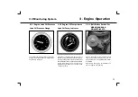
* At temperatures below -20deg C.

kerosene should be added to the diesel
fuel. The relevant percentages are given
in the diagram at the right.

If summer grade diesel fuel must be used
at temperatures below 0 deg.C, up to 60%
kerosene can be added ( see diagram )

Legend :

I

Summer diesel fuel

II

Winter diesel fuel

A

Outside temprature

B

Percentage of kerosene to be
added

Mix in tank only. Fill with the
appropriate amount of
kerosene first, then the diesel
fuel.

Diesel fuels must never be
mixed with petrol

Summary of Contents for HA 294

Page 1: ......

Page 2: ...e Description 7 22 3 Engine Operation 23 34 4 Operating Media 35 38 5 Routine Maintenance 39 44 6 Service Maintenance 45 68 7 Faults Causes Remedies 69 72 8 Engine Preservation 73 76 9 Technical Speci...

Page 3: ......

Page 4: ...We recommend that only trained manpower should perform the operation and maintenance tasks on the engine Always use the genuine Kirloskar spare parts whenever required for periodic maintenance as wel...

Page 5: ...2...

Page 6: ...use and necessary maintenance practices as written in this manual and arises solely from faulty material or workmanship provide always that such defective parts are promptly returned carriage paid to...

Page 7: ...ibutors and Dealers in the case of supplies from their stock and this warranty will come into effect from that time 3 The cost of maintenance or regular service of the engine 4 Any damage due to idle...

Page 8: ...ll repair or replace free of charge goods damaged in transit upto the point of delivery by us as specified above This warranty is the only document given by us warranting the Kirloskar HA series engin...

Page 9: ...6...

Page 10: ...7 2 1 Model 2 2 Engine Illustration 2 3 Lube Oil System 2 4 Fuel System 2 5 Engine Cooling System 2 6 Air Inlet System 2 7 Exhaust System 2 Engine Description...

Page 11: ...8...

Page 12: ...ust be given while ordering spares and asking for service 2 1 1 Rating plate 2 1 2 Rating Plate Location For Genset For Industrial ENGINE TYPE Sr No RATING kW hp rpm RATING STD DATE OF MFG KIRLOSKAR O...

Page 13: ...1 Model 2 1 3 Cylinder Numbering 2 1 4 Direct Injection Cylinder are numbered consecutively beginning at the flywheel end Engines are with direct fuel injection to meet high performance and pollution...

Page 14: ...Flywheel Housing 5 Crank Pulley 6 Belt Tension Unit 7 Oil Filler Neck Cap 8 Lube Oil Sump 9 Lube Oil Filter 10 Fuel Filter 11 Air Cowling 12 V Belt 13 Feed Pump 14 Lube Oil Drain Plug 2 2 Engine Illu...

Page 15: ...arging Alternator 16 Starter 17 Crankcase 18 Crankcase Breather 19 Flywheel 20 Rocker Cover 21 Air Intake Manifold 22 Exhaust Manifold 2 Engine Description 2 2 Engine Illustration 2 2 2 Exhaust Side H...

Page 16: ...mp 4 V Belt 5 Crank Pulley 6 Belt Tension Unit 7 Oil Filler Neck 8 Lube Oil Sump 9 Lube Oil Filter 10 Fuel Filter 11 Air Cowling 12 Rocker Cover 13 Feed Pump 14 Lube Oil Drain Plug 2 2 Engine Illustra...

Page 17: ...fold 16 Charging Alternator 17 Starter 18 Crankcase 19 Crankcase Breather 20 Flywheel Housing 21 Flywheel 22 Turbocharger 23 Air Intake Manifold 2 Engine Description 2 2 Engine Illustration 2 2 4 Exha...

Page 18: ...Oil Cooler 7 Lube Oil Filter 8 Relief Valve not shown 9 Oil Gallery 10 Main Bearing 11 Large End Bearing 12 Camshaft Bearing 13 Tappet with groove for pulse fed rocker arm lubrication 2 3 Lube Oil Sys...

Page 19: ...estrictor for lubrication of gears 19 Spray Nozzle for Piston Cooling 20 Connection for Pressure Gauge 21 Oil Pressure Gauge 22 Fuel Pump Connected to Lube Oil Circuit 2 Engine Description 2 3 Lube Oi...

Page 20: ...pe 6 Pipe to Oil Cooler 7 Oil cooler plate type 8 Lube Oil Filter 9 Safety Valve 10 Oil Gallery 11 Main Bearing 12 Big End Bearing 13 Camshaft Bearing 2 3 Lube Oil System 2 Engine Description 2 3 2 HA...

Page 21: ...Bearing 17 Metering Plug 18 Push Rod and Cover Tube 19 Restrictor Hole 20 Nozzle for Piston Cooling 21 Oil Pipe to Turbocharger 22 Oil return Pipe 23 Oil Pressure Gauge 2 Engine Description 2 3 Lube O...

Page 22: ...ter 5 Injection pump 6 Fuel injection pipe 7 Fuel Injector 8 Leak off pipe 9 Fuel overflow line 10 Overflow valve 11 Fuel return line to tank A Clearance keep as far apart as possible Min 200mm 2 4 Fu...

Page 23: ...temperatures The blower is driven by the engine crankshaft pulley through V belts The V belts tension is maintained by belt tensioning unit Air flow from the blower is directed on the liners and cyli...

Page 24: ...il bath air cleaner is 96 98 Figure above shows the construction of dry type air cleaner used on HA series engines Dry type air cleaners are generally used for earth moving construction equipments The...

Page 25: ...sing elbows Increase pipe I D by 1 5 after every 5 meter length of exhaust pipe Expansion bellows flexible pipes should be installed between engine exhaust piping The exhaust pipe outlet should be ben...

Page 26: ...23 3 1 Commissioning 3 2 Starting 3 3 Monitoring System 3 4 Stopping 3 5 Operating Conditions 3 Engine Operation...

Page 27: ...24...

Page 28: ...e mark For oil specs Refer 4 1 Engines are delivered with first fill oil Use only High speed diesel fuel For fuel specs refer 4 2 Never fill the tank while the engine is running Observe cleanliness an...

Page 29: ...Engine Operation 3 1 Commissioning 3 1 4 Fuel System Ventilation 3 1 5 Other Preparations 3 1 6 Additional Maintenance Work Check battery and lead connections Also check cable connection at the start...

Page 30: ...actuate the starter for more than 10 seconds If the engine does not start wait a minute then try again If the engine does not start after two attempts refer to the Diagnosis Chart see 7 1 Where possib...

Page 31: ...ation 3 2 Starting With Cold Start Aid Flame With Cold Start Aid Flame Glow Plug 12V Glow Plug 24V Insert key Position OFF no operating voltage Turn key clockwise Position ON operating voltage Charge...

Page 32: ...m lube oil pressure Refer 9 1 The lube oil temperature gauge pointer should be in green sector while engine is running If the pointer enters the red sector then oil temperature is beyond acceptable li...

Page 33: ...witch Mechanical Shutdown For HA294 Engine Cylinder head temperature switch Set point 175 50 C protects the engine in case of belt failure If the V Belt fails lever 1 of automatic belt tension operate...

Page 34: ...t suddenly switch off the engine when under full load Allow it to run for 5 Minutes without load Turn key anticlockwise to position OFF and remove The Charge Lamp goes out Stop solenoid is connected t...

Page 35: ...drain plug If necessary allow the oil in the oil bath air cleaner and the engine oil to settle at the ambient temperature while checking oil level Below 20 C after removing the starter if necessary s...

Page 36: ...d in extreme cases the starting behavior The engine can be used for operating conditions other than NTP conditions Temp 27deg C R H 60 100m above sea level however power output will have to be derated...

Page 37: ...34...

Page 38: ...35 4 1 Lube Oil 4 2 Fuel 4 Operating Media...

Page 39: ...36 with nt...

Page 40: ...ating behavior will be attained if you take the accompanying oil viscosity diagram as a guide Should be temperature fall temporarily below the limits of the SAE grade selected cold starting may be aff...

Page 41: ...0 deg C Winter grade fuel suitable down to 20deg cel should be used This fuel is usually available from filling stations well in advance of the cold months At temperatures below 20deg C kerosene shoul...

Page 42: ...39 5 1 Maintenance Schedule 5 2 Maintenance Work Completed 5 Routine Maintenance...

Page 43: ...40...

Page 44: ...sion 6 5 3 V Belt 6 5 2 6 5 4 Fuel filter insert pre filter element cartridge 6 2 Fuel filter insert micro filter element cartridge 6 2 Fasteners 9 2 Starter Alternator Valve clearance 6 6 Injector Sa...

Page 45: ...42 5 Routine Maintenance 5 2 Maintenance Work Completed Hours Date Remark Signature Stamp 50 250 500 750 1000 1250 1500 1750 2000 2250 2500 2750 3000 3250 3500 3750 4000...

Page 46: ...43 5 2 Maintenance Work Completed 5 Routine Maintenance Hours Date Remark Signature Stamp 4250 4500 4750 5000 5250 5500 5750 6000 6250 6500 6750 7000 7250 7500 7750 8000...

Page 47: ...44 Hours Date Remark Signature Stamp 8250 8500 8750 9000 5 Routine Maintenance 5 2 Maintenance Work Completed...

Page 48: ...5 6 1 Lubrication system 6 2 Fuel System 6 3 Cooling System 6 4 Combustion Air System 6 5 Belt Drive 6 6 Adjustments 6 7 Accessories 6 8 Engine Cleaning 6 9 Additional Maintenance 6 Service Maintenanc...

Page 49: ...46...

Page 50: ...lphur content less than 0 05 If the sulphur content is above 0 05 to 1 or operating temperature is below 10deg C then oil change intervals should be halved If case fuel containing more than 1 sulphur...

Page 51: ...or vehicle is on a level surface Start the engine if idle Allow the engine warm up Lube oil temperature approx 80 deg C Switch off the engine Place oil tray under the engine Unscrew drain plug Drain...

Page 52: ...y the removed cartridge Clean sealing surface of filter carrier rim Apply light film of oil to rubber seal of new cartridge Assemble the new cartridge by rotating it clockwise Sealing gasket of cartri...

Page 53: ...in tray Discard the removed element and sealing ring Clean the bowl with diesel Lightly oil the new sealing ring Assemble new filter element Assembly sequence centre bolt copper washer bowl spring mac...

Page 54: ...rcial tool Collect driping fuel in a tray Destroy the removed cartridge Clean the sealing surface of filter Apply light film of oil or diesel fuel to the rubber gasket of the new fuel filter cartridge...

Page 55: ...at bottom of bowls and collect the fuel in tray Unscrew the center bolt of bowls and remove bowls fuel inserts Clean the bowl with diesel Change Pre filter insert only Do not change Pre filter insert...

Page 56: ...Filter Fuel Filter With Common Filter Header Lube oil filter fuel filter Spin On type with common filter header can be supplied as an optional feature 6 2 Fuel System 6 Service Maintenance Fuel Filte...

Page 57: ...re high concentrations of chaff and chopped straw in the vicinity of the machine Because applications vary cleaning intervals have to be determined from case to case The cleaning intervals given in th...

Page 58: ...from case to case If dry type air cleaners are used it should be cleaned only in accordance with the service indicator Air cleaner servicing is needed when The red signal is visible and coincides with...

Page 59: ...Bath Air Cleaner Never clean air cleaner with gasoline Dispose off oil in accordance with envornmental regulations Stop the engine and wait for about 15 mins for oil to drain from filter housing Remov...

Page 60: ...ber gasket and replace if necessary Fill oil bowl with engine oil up to mark Assemble filter element Refit oil bowl and reassemble clamp 6 4 Combustion Air Filter 6 Service Maintenance 6 4 3 Cleaning...

Page 61: ...dust in the air cleaner Empty dust ejector valve by pressing apart lips of discharge slot as indicated Clean discharge slot from time to time Remove any caked dirt by pressing together the upper sect...

Page 62: ...light will pass through it In that case replace the element Check rubber sealing ring for damage Replace if necessary Inner safety element should be replaced after every two changes of outer element R...

Page 63: ...belt 2 until the spring is heard or felt to trigger Carefully remove the gauge without altering the position of the indicator arm 1 Read off the valve where the black indicator arm 1 intersects scale...

Page 64: ...bolts Push alternator inwards Remove V belt and place on new belt Push alternator outwards until desired belt tension is achieved Retighten alternator mtg bolts Fit fan V belts If the V belts fails pr...

Page 65: ...heck valve clearance between rocker arm toe and valve stem with feeler gauge Feeler gauge of 0 15mm should pass with slight resistance Failing this adjust valve clearance Refer 6 6 2 For permissible v...

Page 66: ...of water Apply petroleum jelly vaseline on terminals posts Never apply grease Ensure good contacts of terminals Remove cell caps 1 Top up only with distilled water maintained the level corresponding t...

Page 67: ...y charged 1 20 1 12 Half charged Recharge 1 12 1 08 Discharged Charge up immediately The gases emitted by the battery are explosive Keep spark and naked flames away from the battery Do not allow batte...

Page 68: ...Accessories 6 Service Maintenance Always use proper lifting tackle when transporting and lifting the engine After transportation lifting engine remove lifting tackle before starting the engine Use onl...

Page 69: ...necessary Blow the engine with compressed air to remove water Stop the engine Release the cowling clamps and remove cowling Remove baffle on exhaust side Cover electrical electronic components Starter...

Page 70: ...rrectly inlet manifold heats up in the vicinity of flame heater when starting with preheating Move speed adjustment lever and shut off lever to stop position Insert key Position OFF no operating volta...

Page 71: ...age 3 Loosen pipe connection 1 Remove flame glow plug 2 and reconnect pipe Rotate engine with starter key switch in START position Fuel must be emitted at flame glow plug 2 replace plug 2 if necessary...

Page 72: ...69 7 1 Diagnosis Chart 7 Faults Causes Remedies...

Page 73: ...70...

Page 74: ...orn out valves valve guides Incorrect valve fuel timing Injector needs adjustment Engine seized Faulty governor setting One or more cylinders not working Loose mounting bolts Loose flywheel wrong alig...

Page 75: ...73 8 1 Preservation 8 Engine Preservation...

Page 76: ...74...

Page 77: ...ive ratio 5 1 Refill the fuel tank with mixture Run the engine for 5 mins at low speed fix speed engine at No Load Stop the engine Turn the engine manually several times to preserve the cylinders and...

Page 78: ...missioning Preserved Engine Remove plugs tapes from inlet port exhaust port and vent Remove the rust preventive coating from all external surfaces Install V belts Retension belts after brief operation...

Page 79: ...77 9 1 Engine Specifications 9 2 Power Output 9 3 Torque Wrench Setting 9 Technical Specifications...

Page 80: ...78...

Page 81: ...king from FWE 10 Starting arrangement Electric Start 11 Firing order 1 2 1 3 2 1 3 4 2 1 5 3 6 2 4 1 3 4 2 1 5 3 6 2 4 12 Power Refer 9 2 1 9 2 2 13 Speed Refer 9 2 1 9 2 2 14 Lubrication Force feed G...

Page 82: ...ing order 1 2 1 3 2 1 3 4 2 1 2 4 5 3 1 5 3 6 2 4 1 3 4 2 1 5 3 6 2 4 12 Power Refer 9 2 3 13 Speed Refer 9 2 3 14 Lubrication Force feed G rotor pump 15 SAE oil K Oil Super SAE 15W40 16 Lube oil temp...

Page 83: ...tions 9 2 1 CPCB Compliant ENGINE SPEED Continuous Power as per MODEL rpm ISO 3046 RATING kw bhp HA294 1500 14 0 19 0 1500 15 0 20 5 HA394 1500 23 5 32 0 HA494 1500 31 6 43 0 HA694 1500 47 5 65 0 HA49...

Page 84: ...hp kgm bhp kgm 2300 20 2 27 5 0 084 8 55 HA294 2150 19 5 26 5 0 086 8 85 2000 18 4 25 0 0 087 8 95 1800 16 9 23 0 0 09 9 15 2300 34 6 47 0 0 143 14 6 HA394 2150 32 4 44 0 0 143 14 6 2000 30 2 41 0 0 1...

Page 85: ...85 28 0 9 35 29 5 9 85 2300 20 2 27 5 0 084 8 55 29 0 9 00 30 5 9 50 2500 30 5 8 70 32 0 9 20 1500 23 6 32 0 0 150 15 30 34 0 16 25 36 0 17 20 1800 28 0 38 0 0 148 15 10 40 0 15 90 42 0 16 70 HA394 2...

Page 86: ...57 4 78 0 0 304 31 0 82 0 32 6 87 0 34 6 HA694 2000 62 6 85 0 0 298 30 4 90 0 32 2 95 0 34 0 2150 66 2 90 0 0 294 30 0 95 0 31 6 100 0 33 3 2300 69 9 95 0 0 290 29 6 100 0 31 15 106 0 33 0 2500 106 0...

Page 87: ...3rd 4th ANGLE Nm kgm STAGE STAGE STAGE STAGE Cylinder Head Bolt M12x1 75x211 30 3 1 45 45 45 30 165 See foot Note 1 Connecting Rod Bolt M12x1 5x55 30 3 1 60 30 90 Bearing Cap Bolt M14x110 30 3 1 60 4...

Page 88: ...86...

Reviews: