background image

HIGH PRESSURE PIPE ASSEMBLY

Sr.


No.


Part No.


Description


Qty.


Remark


1


P08.0706.010.0.PR


HIGH PRESSURE PIPE ASSEMBLY


1


RECOIL STARTER ASSEMBLY

Sr.

No.

Part No.

Description

Qty.

Remark

&&

5(&2,/67$57(5 $66(0%/<

.,5/26.$52,/(1*,1(6/,0,7('

$.LUORVNDU*URXS&RPSDQ\

Summary of Contents for KMW MIN T 8 DLX

Page 1: ...Dt D E d y...

Page 2: ...VWHU RXU SURGXFW ZDUUDQW E VXEPLWWLQJ GXO ILOOHG ZDUUDQW UHJLVWUDWLRQ DUG WR 2 GHDOHU H DUH SURYLGLQJ WKUHH ODERXUV IUHH 6HUYLFHV ZLWKLQ VL PRQWKV RI SXUFKDVH UHTXHVWHG WR XWLOL H RXU VHUYLFHV DFFRUGL...

Page 3: ...5 26 5 2 1 1 6 0 7 LUORVNDU URXS RPSDQ...

Page 4: ...7 3 5 2 32 8 1 6 55 17 5 675 7 21 5 7 1 63 7 216 0 1 7 6 7 35 87 21 1 2 6 21 76 21752 6 48 30 17 6 23 5 7 1 16758 7 21 0 17 1 1 6 59 67 57 1 67233 1 2 7 0 1 7528 6 227 1 3 576 7 2 8 6 59 283216 67 3 6...

Page 5: ...Service maintenance is not carried out as per periodical maintenance schedule 4 Warranty voids if KOEL genuine parts or approved blades are not used on machine during periodical maintenance 5 The war...

Page 6: ...I WKH 5 RPSDQ RS Customer s Signature DFNQRZOHGJH WKDW KDYH UHDG XQGHUVWRRG DQG DFFHSW WKH ZDUUDQW SROLF DQG WHUPV H SODLQHG LQ KDSWHU Dealer s Seal Signature Use of MIN T RUHVW 3URIHVVLRQDOV 2UFKDUG...

Page 7: ......

Page 8: ...h Idle rpm 3150 Type of Starting Recoil Type Manual Electric Start Transmission No of Speeds 5 3 forward 2 reverse with Differential lock Working speed 1 25 2 5 9 25 kmph Clutch Dry Double Cone type R...

Page 9: ...e of any sort of intoxicants b Be adequately trained on MINT 8 DLX and when required c Obtain and read the operator s manual before using the MINT 8 DLX for the first time and when required d Wear sui...

Page 10: ...Fuel or lubricants 4 Never place your hands feet or any part of your body near or under any moving part while the MINT engine is running 5 Do not touch the muffler and engine when the machine is in us...

Page 11: ...he fuel cap while engine is running 20 Don t make any adjustment when the engine is in use 21 Handle LH RH and other levers to be used only for controlling the machine 3 4 Recognize Decals Information...

Page 12: ...ttle Control Lever The throttle lever controls the engine speed and tine rotations Moving the throttle lever in the direction shown run the engine faster or slower To increase engine RPM pull the leve...

Page 13: ...e models a PTO reverse lockout device prevents shifting into reverse with the tiller engaged But the lockout disengages automatically during operation with a front mount attachment on the unit When a...

Page 14: ...rt Daily Free Service Period from date of delivery Frequency 20 hrs 30 days 100 hrs 75 days 100 hrs 75 days 200 hrs 150 days Clean Crank Case C C C Engine Oil I R R R Clean Air cleaner I C C C Fuel Le...

Page 15: ...gine is warm to assure rapid and complete draining After complete oil drain out tighten the drain plug securely Fill recommended new engine oil to the outer edge of the oil filler hole Use funnel to a...

Page 16: ...and oil filer cap After complete oil drain out reinstall the drain plug securely fill recommended transmission oil into the gear box Use funnel to avoid oil spilling Use oil filler gun or oil applica...

Page 17: ...everything except the engine immediately after use But to avoid cracking the engine you must let it cool before hosing it down You may however idle the engine until it is warm enough to evaporate the...

Page 18: ...ll level 2 All other attachments Remove dirty grease and lubricate the PTO coupling of the Attachment with bearing grease whenever greasing the unit PTO 6 9 Coupling Attachment To PTO When the PTO fla...

Page 19: ...s from the tractor PTO studs and the two bolts and nuts from the quick hitch 3 Attach the female part pin side up to the tractor PTO Attach the male part hole side up to the attachment connecting flan...

Page 20: ...ttom holes raises the depth gauging knife for maximum tilling depth Warning Obstruction such as rocks and tree roots in the soil can cause blade breakage bending where the machine suddenly jerks or le...

Page 21: ...the clutch lever dislodges the wire spring latch letting you take over control of the clutch If you let go of the handlebar the engine will be switched to a stop 7 4 Cranking to start Turn the ignitio...

Page 22: ...r selection 7 8 Gear and PTO engagement 1 Start the engine and take control of the unit Keep the throttle at moderate speed setting 2 Hold the clutch lever left handlebar depressed while shifting and...

Page 23: ...Engine compression as recommended If found less remove Cylinder head and check valve seat leakage rework it If found ok then check Piston Rings butt gap and Piston to Liner Clearance Any of those fou...

Page 24: ...it If found ok then check Piston Rings butt gap and Piston to Liner Clearance Any of those found more gaps then replace it Engine Starts But Fires Intermittently Stops Sr No Cause Action Taken 1 Air F...

Page 25: ...5 26 5 2 1 1 6 0 7 LUORVNDU URXS RPSDQ...

Page 26: ...SYSTEM CC1 004 5 AIR FILTER ASSEMBLY P08 0710 6 INJECTOR ASSEMBLY CC1 190 3 7 FUEL INJECTION PUMP ASSEMBLY P08 0705 8 HIGH PRESSURE PIPE ASSEMBLY P08 0706 010 0 PR 9 FUEL TANK AND BRACKET P08 0709 10...

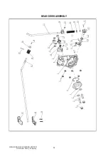
Page 27: ...ENGINE BLOCK CRANK CASE 5 26 5 2 1 1 6 0 7 LUORVNDU URXS RPSDQ...

Page 28: ...5 17 CC3 001 027 0 00 CRANKCASE COVER 1 18 CC3 001 035 0 00 MAIN BUSHING 1 19 CC3 001 028 0 00 ALUMINUM PLUG 0 8 x 8 1 20 CC3 001 56 0 00 OIL GUIDE 1 21 CC3 001 026 0 00 BEARING 6206 1 22 CC3 001 032...

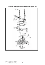
Page 29: ...CYLINDER HEAD ROCKER ARM COVER ASSEMBLY 5 26 5 2 1 1 6 0 7 LUORVNDU URXS RPSDQ...

Page 30: ...002 011 0 00 CLIP A 2 13 CC3 002 012 0 00 ROCKER ARM SCREW M6 x 1 x 32 2 14 CC3 002 013 0 00 ROCKER NUT M6 2 15 CC1 300 15 0 00 FLANGE BOLT M8 x 1 25 x 45 2 16 CC3 002 30 0 00 CYLINDER HEAD ASSEMBLY...

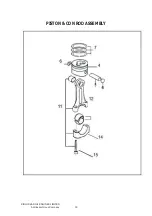
Page 31: ...PISTON CON ROD ASSEMBLY 5 26 5 2 1 1 6 0 7 LUORVNDU URXS RPSDQ...
Page 32: ...PISTON RING GROUP 1 CONSISTING OF SR NO 8 TO 10 8 CC3 005 001 0 00 TOP COMPRESSION CHROME PLATED RING FOR 78 DIA PISTON 1 NOT ILLUSTRATED 9 CC3 005 002 0 00 TAPER FACE SECOND COMPRESSION RING FOR 78...

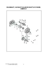
Page 33: ...CRANKSHAFT CAMSHAFT BALANCER SHAFT FLYWHEEL ASSEMBLY 5 26 5 2 1 1 6 0 7 LUORVNDU URXS RPSDQ...

Page 34: ...13 CC3 006 012 0 00 FLYWHEEL NUT WASHER 1 15 CC1 005 33 0 00 FLANGE BOLT M6x 1 x 20 3 16 CC3 006 017 0 00 CABLE HOLDER CLAMP 1 17 N11 051 06 0 00 FLANGED SCREW M6 x 1 0 x 12 mm 1 1 CC3 007 10 0 00 CAM...

Page 35: ...LUBRICATION AND SPEED CONTROL SYSTEM 5 26 5 2 1 1 6 0 7 LUORVNDU URXS RPSDQ...
Page 36: ...29 5 2 5 1 1 1 6 5 0 PP 2 7 5 216 67 1 2 65 12 72 8 2 7 5 6 5 1 6 1 5 2 7 0 2 3803 5 9 1 5 29 5125 5 66 0 216 67 1 2 65 12 72 2 3803 5 9 1 5 29 5125 5 29 5125 7 29 5125 3 1 29 5125 25 7 33 7 25 9 5 6...

Page 37: ...BLY Sr No Part No Description Qty Remark 1 7 0 1 2 66 0 216 67 1 2 65 12 72 1 7 0 1 2 6 7 1 7 0 1 2 5 1 5 6 7 5 1 5 28 1 6 7 6 5 0 6 7 6 5 0 3 35 1 3 3 25 5 7 5 3 35 5 7 5 66 0 5 26 5 2 1 1 6 0 7 LUOR...

Page 38: ...ty Remark 1 725 66 0 25 1 1 3 530 216 67 1 65 12 72 1 725 25 1 1 3 530 63 5 6 9 25 1 725 127 8675 7 02817 1 1 25 1 725 127 8675 7 8 29 5 2 211 7 21 25 1 725 127 8675 7 35 12 6 5 7 1 66 PP 127 8675 7 1...

Page 39: ...USTING GASKET 0 2 1 CC1 014 022 0 00 FUEL INJECTOR PUMP ADJUSTING GASKET 0 3 1 CC1 014 023 0 00 FUEL INJECTOR PUMP ADJUSTING GASKET 0 4 1 CC1 014 009 0 00 FUEL INJECTOR PUMP ADJUSTING GASKET 0 5 1 3 C...

Page 40: ...PE ASSEMBLY Sr No Part No Description Qty Remark 1 P08 0706 010 0 PR HIGH PRESSURE PIPE ASSEMBLY 1 RECOIL STARTER ASSEMBLY Sr No Part No Description Qty Remark 5 2 67 57 5 66 0 5 26 5 2 1 1 6 0 7 LUOR...

Page 41: ...ANK WITH BRACKET 1 2 50 508 08 0 00 COPPER WASHER 10 x 16 1 NOT ILLUSTRATED 3 CC1 010 006 0 00 FUEL HOSE 50 mm 1 4 50 519 02 000 HOSE CLIP n16 2 5 P08 0709 002 0 PR SPECIAL BANJO FOR FIP 1 6 P08 0709...

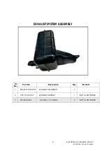
Page 42: ...EXHAUST SYSTEM ASSEMBLY Sr No Part No Description Qty Remark 3 35 867 6 1 5 867 6 7 127 8675 7 187 0 5 127 8675 7 5 26 5 2 1 1 6 0 7 LUORVNDU URXS RPSDQ...

Page 43: ...INJECTOR LEAKOFF ASSEMBLY Sr No Part No Description Qty Remark 3 35 2 3 3 66 0 127 8675 7 8 26 PP 520 1 725 72 7 1 26 3 Q 3 35 63 1 2 8 26 2 00 8 26 2 00 5 26 5 2 1 1 6 0 7 LUORVNDU URXS RPSDQ...
Page 44: ...VARIABLE SPEED MECHANISM Sr No Part No Description Qty Remark 3 35 9 5 63 0 1 60 5 26 5 2 1 1 6 0 7 LUORVNDU URXS RPSDQ...

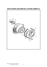
Page 45: ...WIND LEADING CASE ASSEMBLY COWLING ASSEMBLY 5 26 5 2 1 1 6 0 7 LUORVNDU URXS RPSDQ...

Page 46: ...2 1 1 6 7 6 2 625 5 216 67 1 2 65 12 6 2 625 5 2 5 2 1 1 6 1 2 7 0 3 1 6 5 0 2 PP 7 PP 1 1 3 7 66 0 216 67 1 2 65 12 1 1 3 7 2 5 2 1 1 3 7 7 3 216 67 1 2 65 12 2 5 2 1 1 3 7 3 6 2 62 7 21 3 2 1 1 3 7...

Page 47: ...8 7 5 9 35 0 5 3803 3 35 26 3 3 8 7 5 72 35 0 5 3803 3 35 8 3 3 8 7 1 72 8 7 5 3 35 8 3 3 35 0 5 3803 72 3 63 1 2 2 7 25 8 7 5 1 2 2 7 0 25 35 0 5 233 5 6 5 6 7 2 7 0 6 5 0 1 2 7 0 1 1 187 0 26 03 72...

Page 48: ...ER ASSEMBLY D005 6 REAR COVER ASSEMBLY D006 7 HANDLE BAR MOUNTING ASSEMBLY D007 8 HANDLE BAR ASSEMBLY D008 9 DRIVE WHEEL SYSTEM D009 10 ROTOR TILLER AND COVER ASSEMBLY EARTHING UP TYPE D015 11 ROTOR T...

Page 49: ...08 030 FLANGE BOLT M8 30 4 4 P08 D001 041 O 00 HOUSING ADAPTOR 1 5 P08 D001 003 0 00 ADJUSTING PLAIN WASHER M18 1 6 P08 D001 002 0 00 STUD M8 71 6 7 50 911 10 045 FLANGE BOLT M10 45 4 8 P08 D001 081...

Page 50: ...CLUTCH ASSEMBLY SR NO PART NO PART DESCRIPSION QTY 1 P08 D002 025 0 00 CLUTCH ASSEMBLY 1 CONSISTING OF 2 TO 11 11 P08 D002 022 0 00 CONICAL BUSH 1 5 26 5 2 1 1 6 0 7 LUORVNDU URXS RPSDQ...

Page 51: ...M8 41 7 P08 D003 042 0 00 RATCHET CLUTCH 8 P08 D003 053 0 00 SPLINE SHAFT 9 P08 D003 002 0 00 DIFFERENTIAL CLUTCH SPRING 10 50 911 06 016 FLANGE BOLTS M6 16 1 11 P08 D003 012 0 00 STAY FIXED HEX NUT M...

Page 52: ...P08 D003 056 0 00 RIGHT SPLINE SHAFT 34 50 008 08 000 LOCKNUT M8 35 P08 D003 083 0 00 UMBRELLA TOOTH LEFT SEAT 36 P08 D003 057 0 00 BEVEL GEAR 2 37 P08 D003 058 0 00 BEVEL GEAR 1 38 P08 D003 059 0 00...

Page 53: ...RING 12 9 P08 D004 024 0 00 OIL SEAL 38X55X7 10 P08 D004 001 0 00 FUNCTIONAL CLUTCH GEAR POSITIONING SPRING 11 P08 D004 002 0 00 FUNCTIONAL CLUTCH GEAR POSITIONING STEEL BALL 12 P08 D004 056 0 00 OUTP...

Page 54: ...0 DIPSTICK ASSY 10 P08 D005 082 0 00 SUPPORT FOR BATTERY MOUNTING BRACKET 11 P08 D005 024 0 00 SWITCH OFF WIRE 12 P08 D005 083 0 00 CABLE SUPPORT 13 57 076 06 016 ALLEN SCREW M6X16 14 57 006 06 000 NU...

Page 55: ...REAR COVER ASSEMBLY 5 26 5 2 1 1 6 0 7 LUORVNDU URXS RPSDQ...

Page 56: ...00 ELASTIC CYLINDRICAL PIN 4 20 17 P08 D006 043 0 00 ROCKER HEAD 1 18 P08 D006 044 0 00 SMALL ROCKLE 1 19 P08 D006 006 0 00 ELASTIC CYLINDRICAL PIN 6 25 1 20 P08 D006 023 0 00 FLAT GASKET 14 20 2 1 2...

Page 57: ...HANDLE BAR MOUNTING ASSEMBLY 5 26 5 2 1 1 6 0 7 LUORVNDU URXS RPSDQ...

Page 58: ...08 D007 026 0 00 UNDER HANDLE PLASTIC COVER 1 14 P08 D007 001 0 00 CROSS RECESSED COUNTERSUNK HEAD SCREWS ST4X20 2 15 P08 D007 002 0 00 U SHAPE BOLT M8 2 16 P08 D007 071 0 00 ARM CONNECTING BODY 1 17...

Page 59: ...P08 D008 052 0 00 PIN 2 6 P08 D008 081 0 00 AUTOMATIC LOADER 1 7 50 008 06 000 LOCK NUT M6 2 8 P08 D008 082 0 00 PROTECTIVE COVER MOUNTING CARD 2 9 P08 D008 083 0 00 PROTECTIVE COVER FOR HANDLE 2 10...

Page 60: ...0 00 UPPER CLUTCH CABLE ASSEMBLY 1 31 P08 D008 027 0 00 CLUTCH CABLE ASSEMBLY 1 32 P08 D008 054 0 00 UPPER CLUTCH HANDLE SCREW SHAFT 1 33 P08 D008 028 0 00 UPPER CLUTCH HANDLE RESET SPRING 1 34 P08 D0...

Page 61: ...TILLER RIGHT BLADE 4 8 P08 D011 022 0 00 REAR TINE TILLER LEFT BLADE 4 9 P08 D015 001 0 00 SPECIAL BOLT M8 35 8 10 P08 D015 031 0 00 ROTAVATOR SHAFT LEFT 1 11 P08 D015 072 0 00 ROTAVATOR SHAFT RIGHT...

Page 62: ...LANGE BOLTS M12 90 1 36 57 507 12 000 PLAIN WASHER M12 1 37 50 008 12 000 LOCK NUT M12 1 38 57 507 10 000 PLAIN WASHER M10 4 39 P08 D015 082 0 00 LARGE PANEL 1 40 P08 D015 083 0 00 TILLAGE DEPTH ADJUS...

Page 63: ...8 D015 071 0 00 SPLINE CONNECTING SEAT 2 7 P08 D011 023 0 00 REAR TINE TILLER RIGHT BLADE 10 8 P08 D011 022 0 00 REAR TINE TILLER LEFT BLADE 10 9 57 002 06 035 HEX BOLT M6X35 16 10 P08 D011 071 0 00 R...

Page 64: ...D015 029 0 00 O RING 21 1 32 57 507 08 000 PLAIN WASHER M8 1 33 50 911 06 016 FLANGE BOLT M6X16 1 34 P08 D011 083 0 00 RIGHT SIDE PLATE 1 35 50 911 12 090 FLANGE BOLTS M12X90 1 36 57 507 12 000 PLAIN...

Page 65: ...30X42X8 6 P08 D009 002 0 00 CIRCLIP FOR SHAFT 25 7 P08 D009 041 0 00 HUB FOR REDUCTION UNIT WHEEL 8 P08 D005 003 0 00 SCREW M8X25 9 57 002 10 40 HEX BOLT M10X40 10 P08 D009 081 0 00 INSIDE SEMICIRCLE...

Page 66: ...FH 0RGHO DWH RI 6DOH KDVVLV 1R 1R RI ZRUNLQJ KRXUV QJLQH 1R KDVVLV 1R DWH RI 6HUYLFH 1H W 6HUYLFH XH DWH HDOHU V 6WDPS 6LJQ 2ZQHU V 1DPH 7HFKQLFLDQ V 1DPH 6LJQDWXUH 6LJQDWXUH HDOHU V 6HDO 6LJQDWXUH UG...

Page 67: ...EROWV WR WKH UHFRPPHQGHG WRUTXH GMXVW YDOYH FOHDUDQFH DV UHFRPPHQGHG OHDQ IXHO ILOWHU HOHPHQW FKDQJH LW LI QHFHVVDU 7LJKWHQ WKH URWDU EODGHV 1XWV DQG ROWV 7LJKWHQ WKH KDVVLV VWXG DQG EROWV 7LJKWHQ WK...

Page 68: ...YLEUDWLRQ KHFN HQJLQH VSHHG DQG KXQWLQJ KHFN IRU RLO OHDNDJH 6U 1R 6XSSRUWLYH JJUHJDWHV 0DUN KHFN JHDU ER RLO DQG 7RS XS WKH OHYHO XEULFDWH DOO PRYLQJ SDUWV RI MRLQWV DQG OHYHU KHFN W UH SUHVVXUH KHF...

Page 69: ...P08 501 015 0 PR Kirloskar Oil Engines Limited 13 Laxmanrao Kirloskar Road Khadki Pune Maharashtra 411003 KMW MINT O M XO 201 A Kirloskar Group Company...

Reviews: