Piezoelectric Pressure Sensor Type 601C/603C
Page
16
60xC_002-741e-08.18
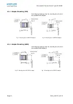
4.3 Manufacturing of mounting hole
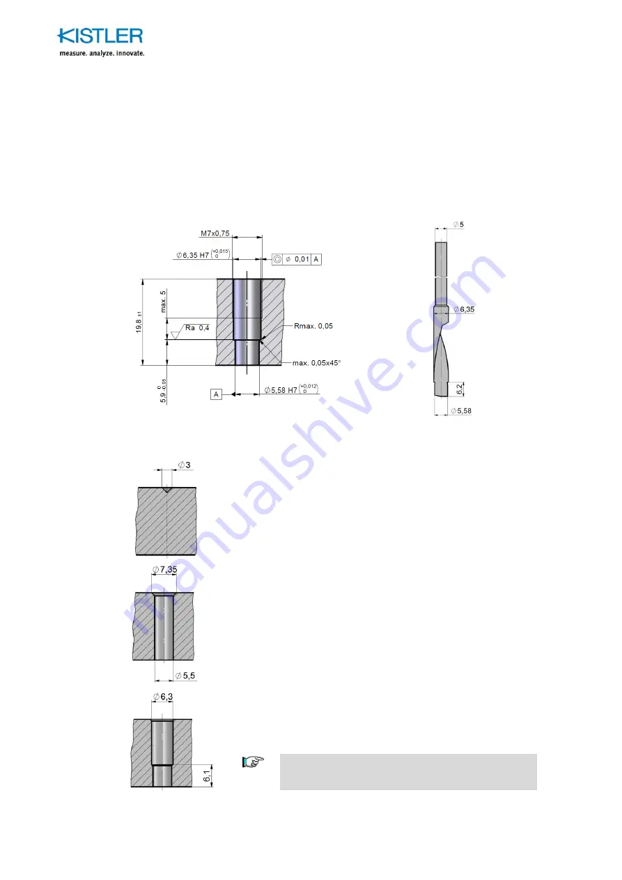
4.3.1 Direct mounting (ISO)
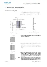
The following procedure is recommended for the manu-
facturing of the direct mounting bore with Kistler step drill
type 1331 and for use with ISO floating clamp nut
6423B00 with a M7x0.75 thread.
Fig. 7: Flush mounting bore
Fig. 8: Kistler step drill, Type 1331
1. Centering hole, use a center drill with 3.0 mm diameter
and 90° chamfer angle.
2. Ø5.5 mm through-hole, use a spiral drill with 5.5 mm
diameter.
Ø7.35 mm countersink at the entrance of the Ø5.5 mm
blind hole, use a countersink cutter with a 90° chamfer
angle.
3. Ø6.3 mm blind hole, use a spiral drill with 6.3 mm
diameter. Select the bore depth accordingly, so that
the front cutting lips of the spiral drill do not undercut
the residual wall thickness of 6.1 mm at the diameter
of 5.5 mm.
A too deep blind hole will damage the contact surface
to the sensor (shoulder) and thus the sealing surface.
This could result in leakage at low pressure.


