Support
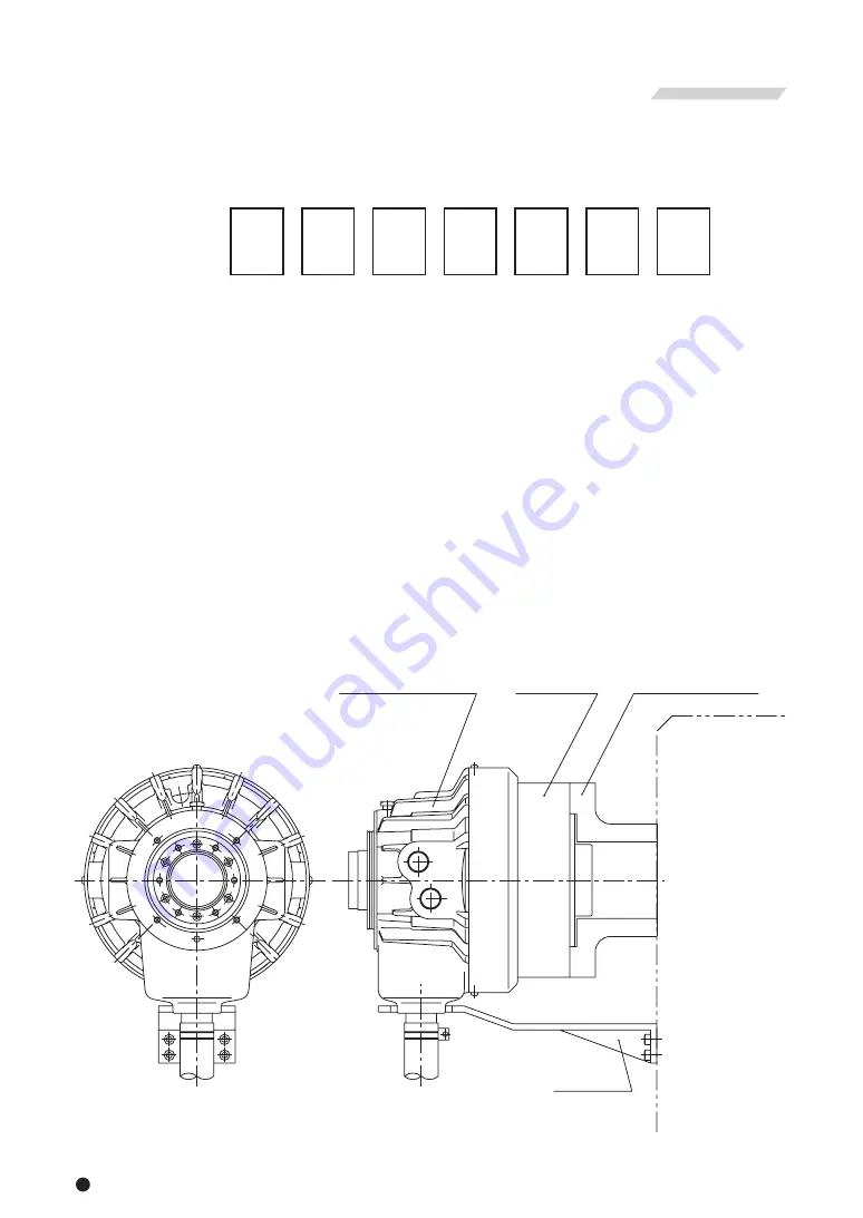
Lathe
Cylinder adapter
Cylinder
Sleeve Body
Cylinder
Chuck
Drain hose
Flexible hose
Solenoid
valve
Line Filter
B
T
P
Dr
A
Tank
Pressure adjusting
screw
Hydraulic
pump
Pressure
gauge
Manual
switching valve
SOL.
3
4
Type display as shown below.
This instruction manual is for the cylinder part.
1−1 Type display
1−3 Scope of product
1−2 Structural drawing
Fig. 1
S
Fig. 2
1 . Structural Drawing and Parts List
・To prevent the work from flying, safe design, maintenance and erroneous action prevention of the hydraulic
system to maintain the gripping force of the chuck is extremely important. Thoroughly read the Important
Safety Precautions on and after page 6 in this manual.
・ As for the chuck, follow the instruction manual for the chuck.
1
Example
12
2
46
3
4
5
6
7
5th digit and after that are not displayed for the standard cylinders.
1. S Abbreviated name of S cylinders
2. 12 Nominal inside diameter of the cylinder
3. 46 Nominal thru-hole diameter
4. − Cylinder with lock valve, relief valve and fan (Standard specification)
L Long stroke type cylinder with lock valve, relief valve and fan
5〜7 Columns for special specification for each destination of delivery
Remarks 1) What is a lock valve ?
This is a valve which has a function to retain the hydraulic pressure inside a cylinder temporarily
when the pump pressure suddenly lowers as a result of blackout, malfunction of the hydraulic
pump, etc.
Remarks 2) What is a relief valve ?
This is a valve which has a function to stop damage when the hydraulic oil filled inside the
cylinder has increased its pressure due to the volume change.
WARNING
Summary of Contents for S1036
Page 31: ......


