22
8-3-3. Hydraulic clamp system (See Fig.4)
Tilt the rotating axis 90°from the horizontal state of table (0°) to make the table vertically.
(See Fig.3-1)
Air relief on rotating axis side
Bleed air on the rotating axis side at two points (
①
,
②
).
1) Clamp the NC rotary table (apply hydraulic pressure).
2) Slightly loosen the screw of air relief plug
①
with the table clamped to allow hydraulic oil to leak a little,
so as to bleed the bubbles (air) contained in the leaking oil. After a while, with the table clamped,
tighten the screw of
①
once, and repeat the clamp and unclamp operation. Again, loosen the screw
of
①
to leak the hydraulic oil a little to bleed the bubbles contained in the oil. Repeat this operation
until the bubbles disappear, and tighten the screw of
①
again. Retain lightly the air relief plug
①
with
a hexagonal wrench key, and with the plug covered with rags, loosen the plug a little to bleed the air.
3) When bubbles (air) mixed with oil does not run over the air relief plug
①
, tighten the air relief plug
①
under a clamp state.
4) Then, bleed the air by means of air relief plug
②
by the same procedure.
5) Repeat the procedure until no bubbles are found in the leaking oil even if any screw of air relief plug
①
or
②
is loosened.
Air relief on tilting axis side
Bleed air on the tilting axis side at one point (
③
).
1) Perform the air relief with the air relief plug
③
by the above steps 1) and 2).
2) When bubbles (air) mixed with oil does not run over the air relief plug
③
, tighten the air relief plug
③
under a clamp state.
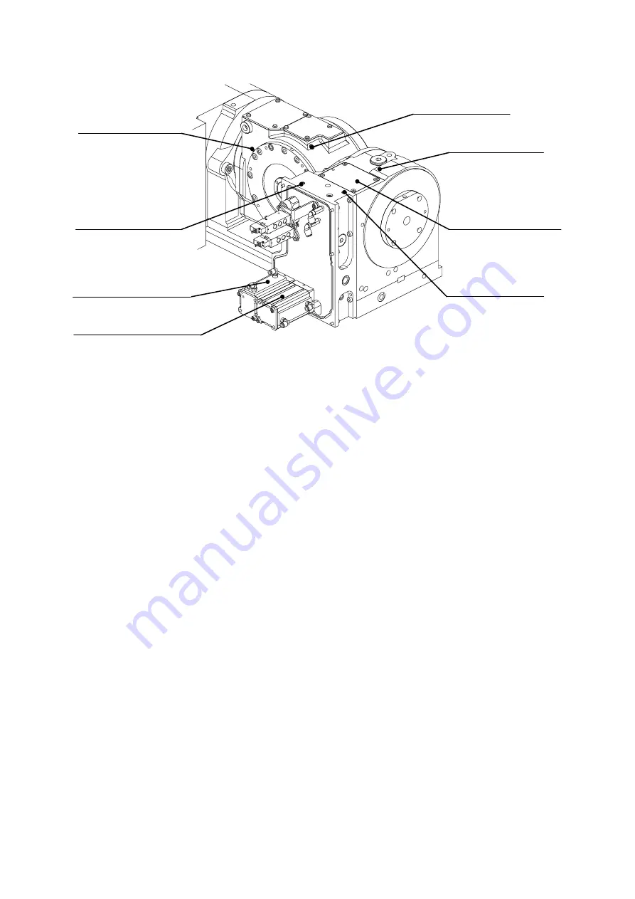
Fig. 3-3
Air relief plug
④
(Rotating axis)
Air relief plug
③
(Rotating axis)
Air relief plug
⑥
(Tilting axis)
Cover (Oil tank)
①
Air relief plug
②
(Rotating axis)
Air relief plug
⑤
(Tilting axis)
Cylinder for tilting axis
Cylinder for rotating axis


